I2773-4.4 en
199
Somat eDAQ
lite
12.5 ELDIO (Digital I/O Layer)
Transducer Cable for Digital I/O and Pulse Counter
The ELDIO layer uses the Somat SAC-TRAN-MP Transducer Cable
(1-SAC-TRAN-MP-2-2 or 1-SAC-TRAN-MP-10-2) with an M8 connector and a set of
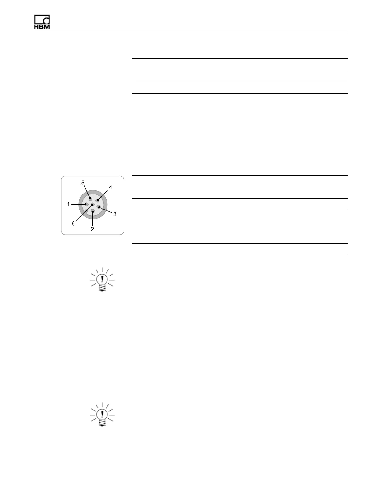
color-coded pigtail wires. The following table lists the pinouts for the SAC-TRAN-MP
cable when used for ELDIO inputs. The I/O pin depends on the bank connector (i.e.,
|1-4|, |5-8| or |9-12|).
NOTE
The quadrature encoder outputs as specified are for default signal polarity which
assigns the positive direction to clockwise rotation. To reverse polarity, interchange
encoder outputs A and B.
12.6 Vehicle Bus Modules (VBM)
The vehicle bus modules use the Somat SAC-TRAN-MP Transducer Cable
(1-SAC-TRAN-MP-2-2 or 1-SAC-TRAN-MP-10-2) with an M8 connector and a set of
color-coded pigtail wires. The following sections list the pinouts for the SAC-TRAN-MP
cable when used with each available VBM interface.
12.6.1 Transducer Cable for VPW Interface
The following table lists the pinouts for the SAC-TRAN-MP cable when used with the
VPW interface.
NOTE
Always provide the +12 volt REF voltage for the VPW module to function.
- Excitation 4 Black
+ Excitation 5 Red
- Signal Input 6 Green
Function Pin Wire Color
Function Pin Wire Color Quad Encoder Usage
I/O 4, 8 or 12 1 Brown Encoder 2, output B
I/O 3, 7 or 11 2 White Encoder 2, output A
GND/Shield 3 bare wire Return
I/O 1, 5 or 9 4 Black Encoder 1, output A
Power 5 Red Power
I/O 2, 6 or 10 6 Green Encoder 1, output B
HBM: public