I2773-4.4 en
203
Somat eDAQ
lite
13 Device Wiring
The following sections provide device wiring diagrams for all applicable layer types. For
more information on using each transducer, see “eDAQlite Hardware” on page 89
and “Input Channels” on page 107. For complete pinouts for the cables used in the
following sections, see “Cable Pinouts” on page 195.
13.1 ELDIO (Digital I/O Layer)
13.1.1 ELDIO Digital Input
Use the Somat SAC-TRAN-MP Transducer Cable (1-SAC-TRAN-MP-2-2 or
1-SAC-TRAN-MP-10-2) to wire ELDIO digital inputs.
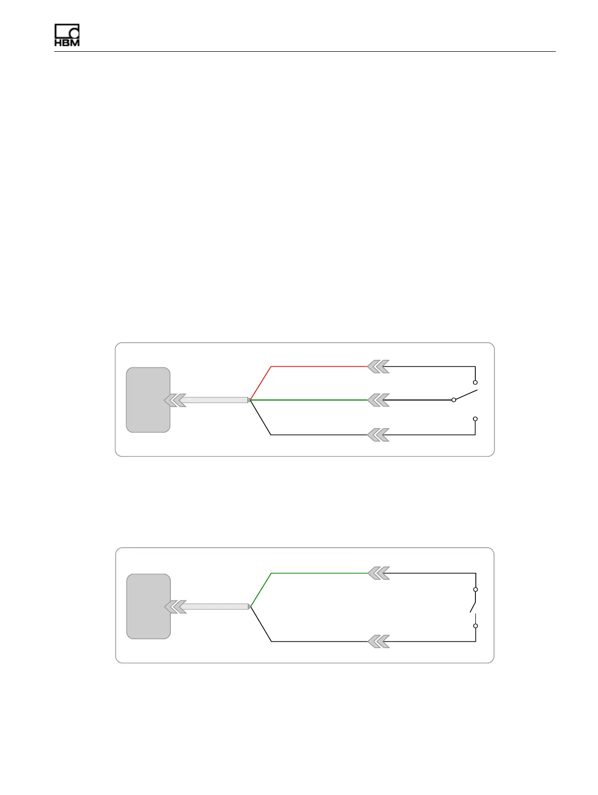
Preferred Switch
Whenever possible, a single-pole, double-throw switch, wired as shown below, should
be used for switched inputs. This circuit solidly switches the input line to either ground
or +5 volts and prevents coupling of the input line to other digital input lines. Moving
the switch to the ground side is identified as FALSE.
Figure 13-1:
Wiring diagram for the preferred switch configuration on an ELDIO input.
Alternate Switch
The following diagram shows the circuit wiring for an alternate digital input involving a
switch closure function. An open switch as shown is TRUE; a closed switch is FALSE.
This circuit is adequate for most applications.
Figure 13-2:
Wiring diagram for the alternate switch configuration on an ELDIO input.
2QYGT8
+15KIPCN
)0&5JKGNF
TGF
'.&+1
5#%64#0/2
+1
+15KIPCN
)0&5JKGNF
'.&+1
5#%64#0/2
+1
HBM: public