I2773-4.4 en
89
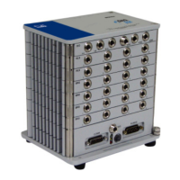
Somat eDAQ
lite
5 eDAQlite Hardware
The following chapter provides details on the input and output channels and
configuration options available on each eDAQ
lite
layer and module. Access the
configuration options through the TCE hardware setup window by double clicking a
hardware entry or highlighting an entry and selecting Config.
NOTE
For information on data synchronization across channels and hardware, see “Data
Synchronization” on page 209.
5.1 ELCPU (Base Processor)
The ELCPU is the foundation of the eDAQ
lite
system. For more information on
eDAQ
lite
capabilities contained in the ELCPU such as battery power, Ethernet
communications and on-board memory, see “Using the eDAQlite” on page 23.
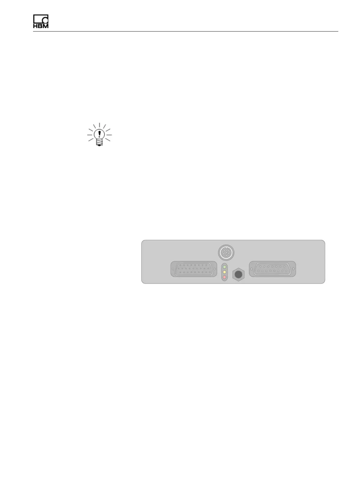
5.1.1 ELCPU Available Inputs
The ELCPU includes a serial port (Comm) which can be used as an input for serial
bus data.
Figure 5-1:
Diagram of the connectors on an ELCPU-PLUS or ELCPU layer including the
9-pin D-Sub Comm port used for serial bus inputs.
Serial Bus
The RS232 serial port can be configured as a data input port to acquire serial data
streams from various sources. Specialized code must be written to deal with the
specifics of the particular serial data streams. Therefore, serial data sources are
supported on a custom basis for such things as serial GPS or customer specific
vehicle buses. Refer to the installation instructions in the firmware installation directory
for more information on installing custom modules. Connect serial data source to the
eDAQ
lite
using the Comm connector on the front panel of the ELCPU layer.
5.1.2 ELCPU Configuration Options
The ELCPU offers several configuration options through the hardware setup window.
The serial bus port appears as a separate entry in the hardware setup window and
has its own configuration options which are identical to the vehicle bus configuration
options. For more information on these options, see “VBM Configuration Options” on
page 99.
HBM: public