I2773-4.4 en
25
Somat eDAQ
lite
Layer Addressing
The eDAQ
lite
stack is configured at the factory with the layer address jumpers
properly set. Follow the guidelines below to reconfigure an eDAQ
lite
stack.
On all eDAQ
lite
layers except the ELCPU, there is a set of three jumper locations
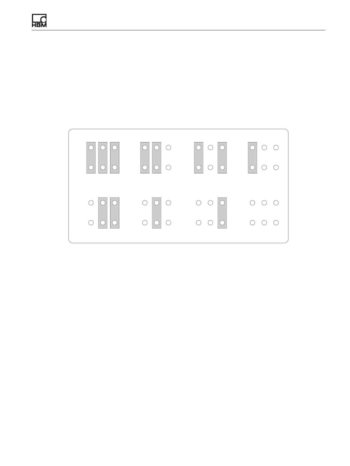
used to assign a physical layer address. Each jumper location consists of two
associated pins labeled 1-2, 3-4 or 5-6 where pins 1-2 represent the least significant
digit and pins 5-6 represent the most significant in a three-digit binary number. A
jumpered pair results in a logical 0. An illustration of all possible logical addresses
follows.
Figure 2-1:
Possible jumper configurations for addressing eDAQ
lite
layers.
All layer address jumper sets are on the side of the bus connector receptacle (i.e.,
opposite the side with the bus connector bare pins). The jumper is labeled JP1 on all
layers.
HBM: public