4-15
DNW-A75/A75P
123
45
6
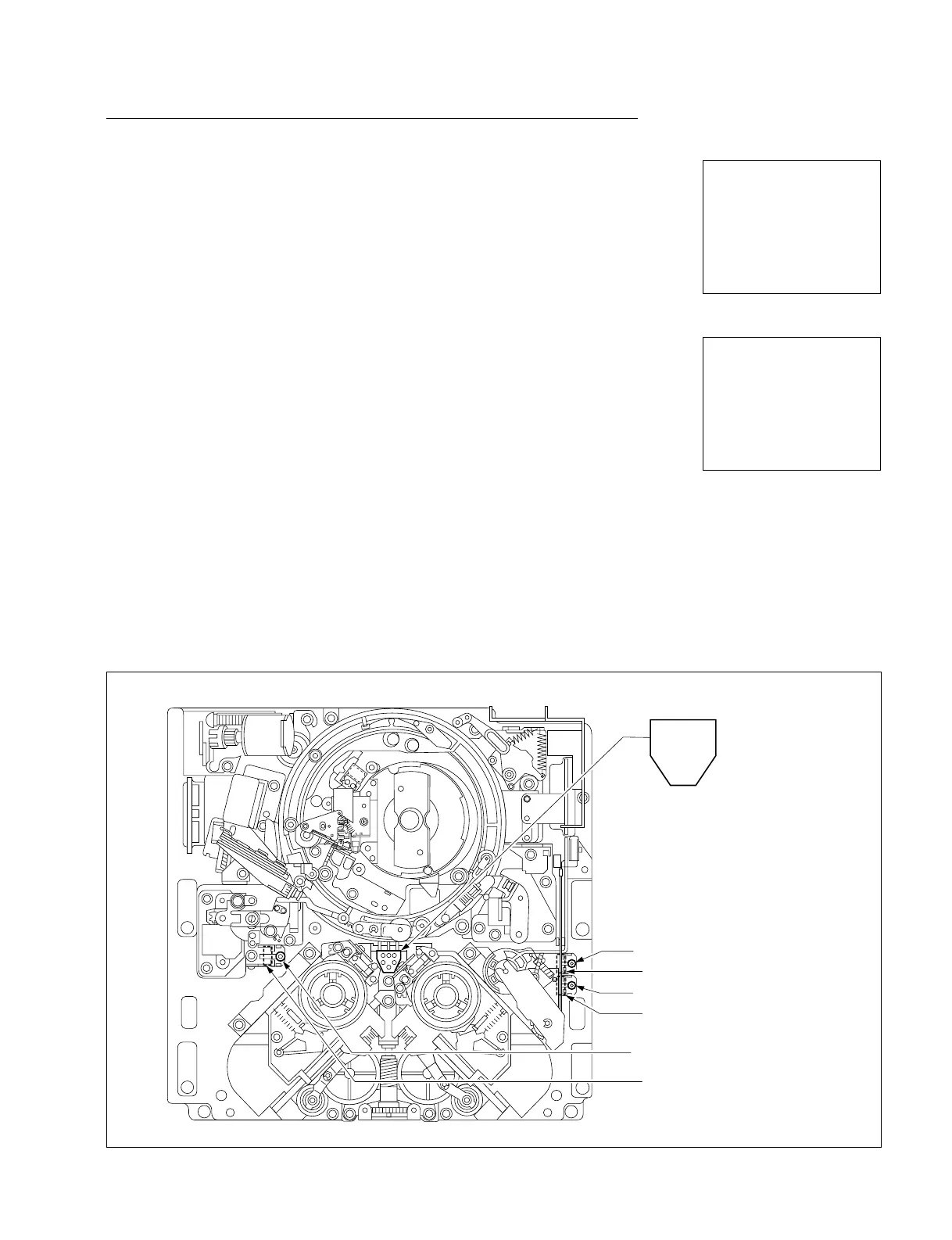
1 Reel hub sensor
2 Metal/oxide tape sensor
3 Tape thickness sensor
4 Spare sensor 2
5 Spare sensor 1
6 Digital/analog tape sensor
9 L cassette (SP) REC inhibit switch
8 L cassette (SX) REC inhibit switch
Sensor
Sensor
Cassette tab sensors
Sensor
7 S cassette REC inhibit switch
SERVO CHECK
INPUT CHECK
C000:CASSETTE SW
1:REEL HUB 2:METAL/OX
3:THICKNESS 4:SPARE
5:SPARE 6:DGTL/ANLG
7:S REC INH 8:L REC INH
9:L SP INH
7 123 9
SW 987654321 4 5 8
000000000 6
SERVO CHECK
INPUT CHECK
C000:CASSETTE SW
1:REEL HUB 2:METAL/OX
3:THICKNESS 4:SPARE
5:SPARE 6:DGTL/ANLG
7:S REC INH 8:L REC INH
9:L SP INH
7 123 9
SW 987654321 4 5 8
001000000 6
(Ex.: When pushing the switch 7)
C000 : CASSETTE SW
This submenu checks the functions of six cassette tab sensors and three REC inhibit
sensors (switches).
Checking
Be sure to check each sensor (switch).
(1) Push a sensor (switch) with a finger, and hold it.
. Check the superimposed display to see that a character below the correspond-
ing SW number changes from “0” to “1”.
(2) Release the sensor (switch).
. Check the superimposed display to see that above-mentioned “1” returns to “0”.
(3) To finish the check, press the MENU button once.
In case of NG
When any cassette tab sensor (1 to 6) is NG:
. Check the corresponding sensor on the PTC-59 board.
. Check the corresponding sensor input port of MPU (IC1 on the MS-58 board).
When any REC inhibit sensor (7 to 9) is NG:
. Check the corresponding sensor on the MS-58 board.
. Check the corresponding sensor input port of MPU (IC1 on the MS-58 board).
Locations of Sensors (Switches)
4-2. TAPE Maintenance Mode (M0)
4-2-2. SERVO CHECK Mode (C00-03)