4-16
DNW-A75/A75P
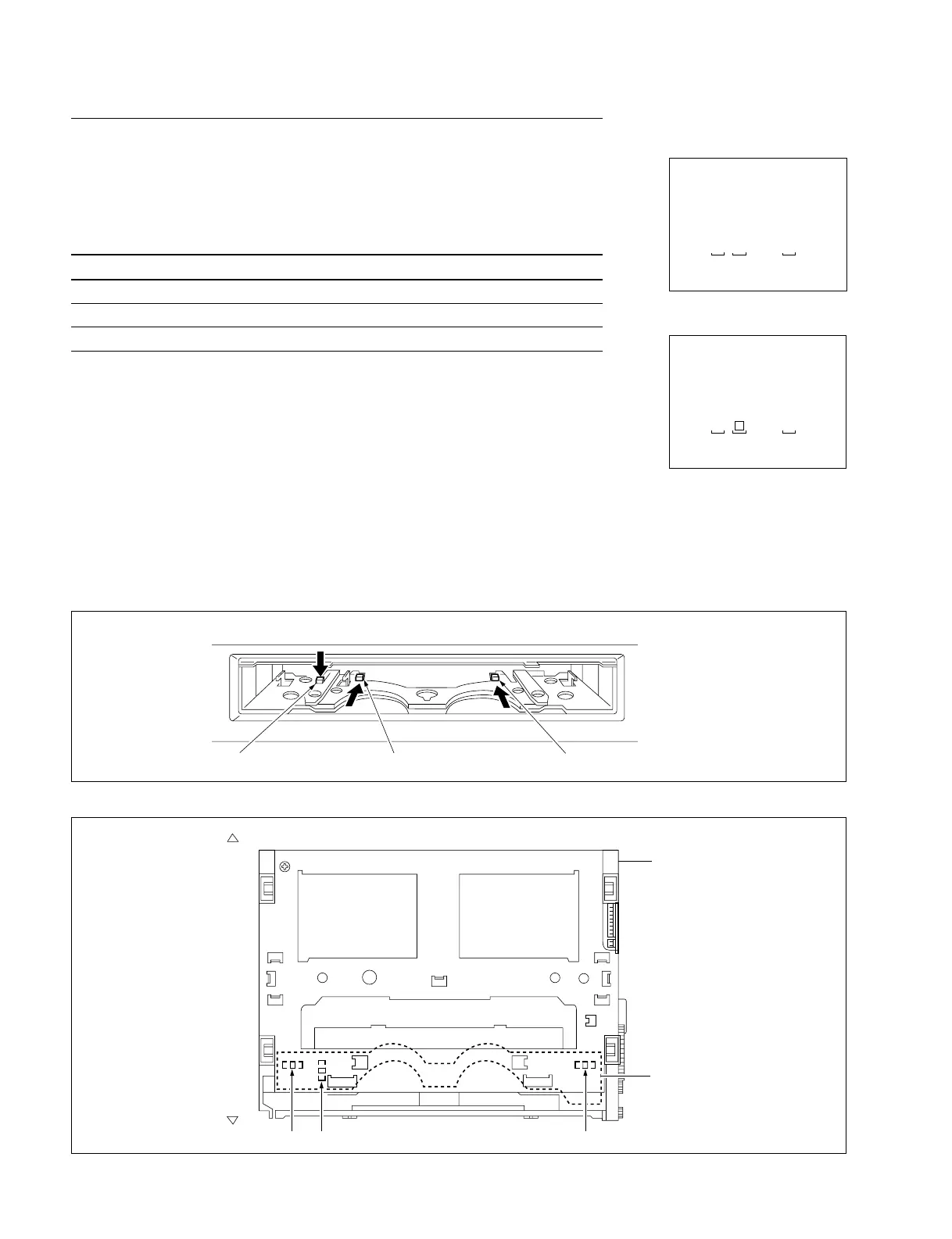
PC-70 board
Cassette compartment
< Top view >
Cassette-in sensor (L) Cassette size sensor Cassette-in sensor (R)
Front
Rear
C001 : CASSETTE COMP. SW
This submenu checks the functions of three sensors (switches) in a compartment.
Checking
Be sure to check each sensor (switch). These switches interlock with sensors.
Switch Sensor
SW1 : Cassette-in switch 1 Cassette-in sensor (L)
SW2 : Cassette-in switch 2 Cassette-in sensor (R)
SW3 : L cassette detection switch Cassette size sensor
(1) Push up the cassette door to the inside with one finger, and hold it.
(2) Push a switch in the direction indicated by the allow with another finger, and hold it.
. Check the superimposed display to see that the corresponding SW number
changes to “[||]”.
(3) Release the switch.
. Check to see that above-mentioned “[||]” returns to the former switch number.
(4) To finish the check, press the MENU button once.
In case of NG
. Check the corresponding sensor on the PC-70 board.
. Check the corresponding sensor input port of MPU (IC1 on the MS-58 board).
4-2. TAPE Maintenance Mode (M0)
4-2-2. SERVO CHECK Mode (C00-03)
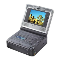
SERVO CHECK
INPUT CHECK
C001:CASSETTE COMP. SW
SW1:CASSETTE IN SW 1
SW2:CASSETTE IN SW 2
SW3:LARGE CASSETTE SW
3 1 2
SERVO CHECK
INPUT CHECK
C001:CASSETTE COMP. SW
SW1:CASSETTE IN SW 1
SW2:CASSETTE IN SW 2
SW3:LARGE CASSETTE SW
3 2
(Ex.)
Locations of Sensors
Locations of Switches in Compartment Block
SW3
SW1
SW2
Push the cassette window up manually. Push the switch in the direction of thick arrow.
 Loading...