5-14
DNW-A75/A75P
C-B head
CNF A headBoard cover
A
Adjustment screwBase plate
Cover
Screw hole
Dial gauge
Leg
Leg
Drum
Positioning
flange
Probe
Drum
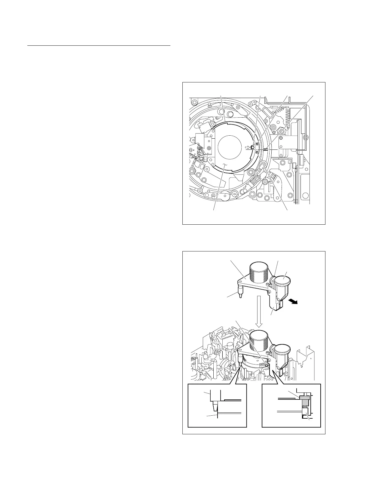
Setting of Head Tip Protrusion Measurement
Gauge
n
Being careful not to damage the tape-running surface and
video heads of the drum, set the gauge.
1. Turn the upper drum manually counterclockwise (3)
to align the screw hole (8 mark on the board cover)
to the rib of the threading ring as shown in Figure 2.
n
The upper drum position is determined as described
above to put the probe of the head tip protrusion
measurement gauge on the absence of a head. The
video head that first measures the protrusion value is
the CNF A head.
2. Check the value that the dial gauge pointer reads.
3. Position a probe between the C-B head and CNF A
head. (Refer to Figure 2.)
4. Press the tip of two legs against the outer circumference
of the drum’s upper surface while keeping the base plate
of the measurement gauge in parallel with the upper
surface of the drum. Be sure to keep the probe of the
measurement gauge sufficiently away from the drum.
5. Lower the measurement gauge slowly until the ridges
of the two legs and positioning flange touch the upper
drum while pushing two legs against the outer circum-
ference of the drum’s upper surface (applying force
slightly to the measurement gauge in the direction
indicated by the arrow). (Refer to Figure 3.)
m
. Before placing a measurement gauge on the drum,
ensure that the adjustment screw has been loosened
fully.
. Perform carefully and slowly so that the probe of a
measurement gauge does not touch the outer circum-
ference or video head on the drum. (Lower so that
the probe is slightly higher than the two legs.)
. After placing the measurement gauge on the drum,
be sure to support it with hand at all time.
If it is loose carelessly, the drum and measurement
gauge will turn and damage the peripheral parts.
6. Check to see the followings:
. The probe is in the middle of the adjacent heads.
. The positioning flange adheres closely to the outer
circumference of the drum’s upper surface.
. The legs adhere closely to the outer circumference of
the drum’s upper surface.
. The value that the dial gauge pointer reads is the
same as before setting (in step 2).
5-3. Video Head Tip Protrusion Check
7. Turn the adjustment screw clockwise until the dial
gauge pointer rotates approximately a half turn.
8. Turn the outer frame of the dial gauge to align zero (0)
to the pointer.
Figure 2. Setting of Drum Position
Figure 3. Setting of Head Tip Protrusion Measurement Gauge