5-15
DNW-A75/A75P
Measurement of Head Tip Protrusion
n
When turning the upper drum manually, hold the cover of
the measurement gauge by your hand to not come to turn
the gauge with the drum rotation.
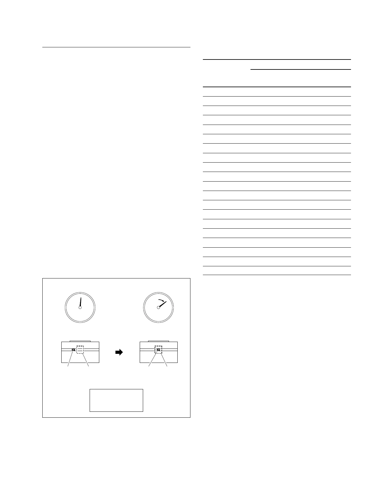
1. Turn the upper drum manually counterclockwise (3)
very slowly to approach a video head aside of the
probe. (Refer to <A> in Figure 4.)
2. Read the dial gauge pointer. (= Ha)
n
The scale of the dial gauge is 2 µm (0.002 mm) pitch.
Clockwise: +. Counterclockwise: _.
3. Turn the upper drum manually counterclockwise (3)
very slowly to center the video head in the probe.
(Refer to <B> in Figure 4.)
4. Read the dial gauge pointer. (= Hb)
5. Calculate the real head tip protrusion Hr with the Ha
and Hb.
Hr = Hb _ Ha
6. Calculate the head tip protrusion Hr for all heads with
steps 1 through 5 performing .
7. Measure and calculate the real head tip protrusion Hr
for all heads again.
n
Do it two times for fear of measuring error.
Figure 4. Example of Head Tip Protrusion Measurement
This table is in measure order of the heads.
Head tip protrusion (Hr = Hb
__
__
_ Ha)
Head Spec.
name (µm) First time Second time
CNF A 22 = _ |=_
CNF B 22 = _ |=_
Dummy _ (No need for measurement)
ADV A5 22 = _ |=_
ADV B5 22 = _ |=_
ADV A6 22 = _ |=_
ADV B6 22 = _ |=_
Y-A 20 = _ |=_
C-A 20 = _ |=_
Erase _ (No need for measurement)
REC A 24 = _ |=_
REC B 24 = _ |=_
Dummy _ (No need for measurement)
ADV A1 22 = _ |=_
ADV B1 22 = _ |=_
ADV A2 22 = _ |=_
ADV B2 22 = _ |=_
Y-B 20 = _ |=_
C-B 20 = _ |=_
Removal of Head Tip Protrusion Measurement
Gauge
1. Turn the upper drum manually counterclockwise (3)
very slowly to move a video head aside from the
probe.
2. Loosen the adjustment screw fully (by turning it
counterclockwise).
3. Lift up the positioning flange from the outer circum-
ference of the drum’s upper surface to a few millime-
ters, and then lift the measurement gauge slowly and
remove it while pushing two legs against the outer
circumference of the drum’s upper surface (applying
force slightly to the measurement gauge in the direc-
tion indicated by arrow A). (Refer to Figure 3.)
n
Perform carefully and slowly so that the probe of a
measurement gauge does not touch the outer circum-
ference or video head on the drum.
0
0
(Ex, Ha=2) (Ex, Hb=40)
40
Dial gauge Dial gauge
Video head A Probe
Video head A Probe
< A > < B >
Hr = Hb _ Ha
= 40 _ 2
= 38 (µm)
5-3. Video Head Tip Protrusion Check