Vi3000 USER MANUAL
5.3 Operations Overview > Console Bays
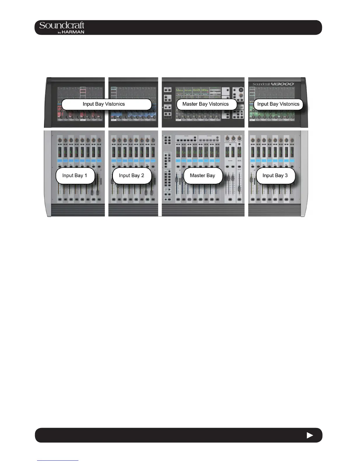
5.3: Console Bays
The Console is divided into four main bays. Counting from the left, the rst, second, and fourth bays are Input Bays.
The third bay is the Master Bay.
Input bays normally control input channels, however, they can have other functions mapped to them depending on
how the console is being used. For example, you can map the bus masters, graphic EQ bands, matrix mix sources,
aux bus contribtions, and more to the input faders.
The input bay vistonics touch screen areas normally show eight channel-strip processing blocks for the eight corre-
sponding faders. You can touch those processing blocks to focus the VST section on that selection.
The input bay VST areas normally show Aux 1 and 2 contributions, though the functions of these encoders are also
determined by the input channel VISTONICS button group.
The Master Bay contains asignable faders for the bus masters, plus the mix master (L, R, C) faders and the assigna-
ble monitor fader. It also
The Master Bay touch screen default display is an overview of metering for all input and output channels, as well as an
as system message area and cue list.
The Master Bay VST area’s default mapping is the rst 16 bus masters. The next eight masters can be accessed with
the [PAGE 2] button in the Master Bay VISTONICS button group.
 Loading...