RM0440 Rev 4 1121/2126
RM0440 Advanced-control timers (TIM1/TIM8/TIM20)
1226
2. The ARR[3:0] bits must be reset
3. The DITHEN bit must be reset
4. The CCIF flags must be cleared
5. The CEN bit can be set ( eventually with ARPE = 1).
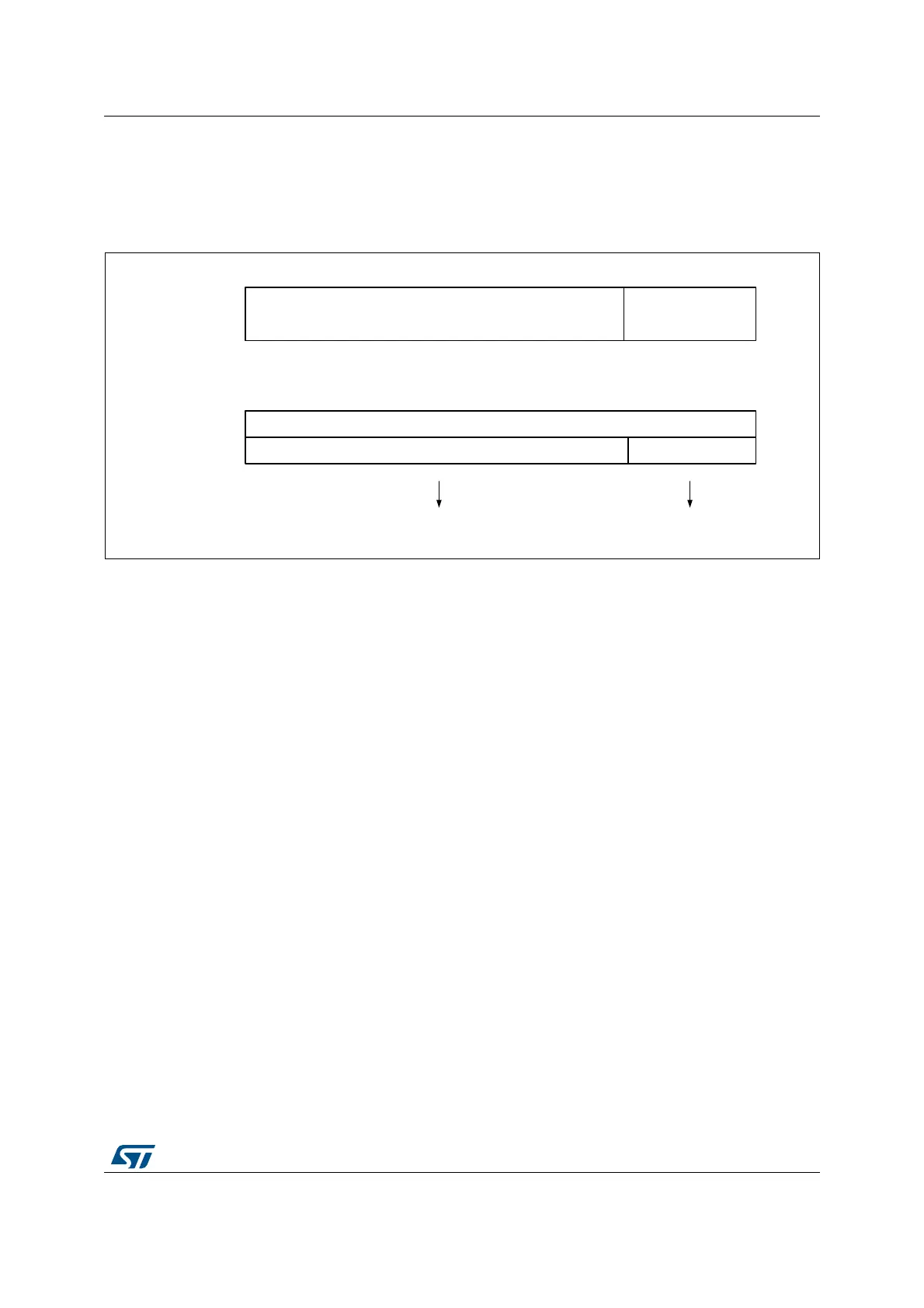
Figure 305. Data format and register coding in dithering mode
The minimum frequency is given by the following formula:
Note: The maximum TIMx_ARR and TIMxCCRy values are limited to 0xFFFEF in dithering mode
(corresponds to 65534 for the integer part and 15 for the dithered part).
As shown on the Figure 306 below, the dithering mode allows to increase the PWM
resolution whatever the PWM frequency.
MSv45753V2
MSB: 16-bits, integer part
LSB: 4-bits
fractional part
326
20 6
Base compare value is 20 during 16 periods
Additional 6 cycles are spread over the
16 periods
Register format in
dithering mode
Example
b0b19
b0b19
Resolution
F
Tim
F
pwm
--------------
F
pwmMin
F
Tim
Max
Resolution
-------------------------------------
==
Dithering mode disabled: F
pwmMin
F
Tim
65536
----------------
=
Dithering mode enabled: F
pwmMin
F
Tim
65535
15
16
------
+
------------------------------
=
 Loading...


