RM0440 Rev 4 1601/2126
RM0440 Universal synchronous/asynchronous receiver transmitter (USART/UART)
1733
Every character is preceded by a start bit which corresponds to a low logic level for one bit
period. The character is terminated by a configurable number of stop bits.
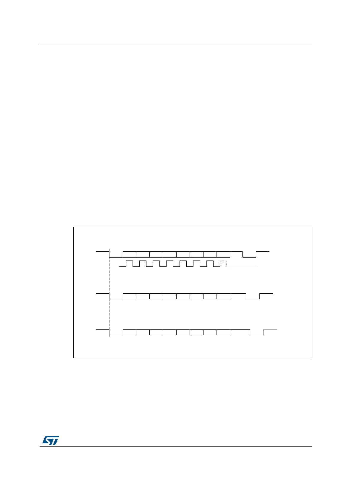
The number of stop bits can be configured to 0.5, 1, 1.5 or 2.
Note: The TE bit must be set before writing the data to be transmitted to the USART_TDR.
The TE bit should not be reset during data transmission. Resetting the TE bit during the
transmission corrupts the data on the TX pin as the baud rate counters get frozen. The
current data being transmitted are then lost.
An idle frame is sent when the TE bit is enabled.
Configurable stop bits
The number of stop bits to be transmitted with every character can be programmed in
USART_CR2, bits 13,12.
• 1 stop bit: This is the default value of number of stop bits.
• 2 stop bits: This is supported by normal USART, Single-wire and Modem modes.
• 1.5 stop bits: To be used in Smartcard mode.
An idle frame transmission includes the stop bits.
A break transmission features 10 low bits (when M[1:0] = ‘00’) or 11 low bits (when M[1:0] =
‘01’) or 9 low bits (when M[1:0] = ‘10’) followed by 2 stop bits (see Figure 532). It is not
possible to transmit long breaks (break of length greater than 9/10/11 low bits).
Figure 532. Configurable stop bits
MSv31887V1
** LBCL bit controls last data clock pulse
Bit7Start bit
Stop
bit
Next
start
bit
Possible
parity bit
Data frame
Next data frame
CLOCK
**
Next data frame
8-bit data, 1 Stop bit
8-bit data, 1 1/2 Stop bits
8-bit data, 2 Stop bits
Bit6Bit5Bit4Bit3Bit2Bit1Bit0
Bit7Start bit
1.5
Stop
bits
Next
start
bit
Possible
parity bit
Data frame
Bit6Bit5Bit4Bit3Bit2Bit1Bit0
Next data frame
Bit7Start bit
2
Stop
bits
Next
start
bit
Possible
parity bit
Data frame
Bit6Bit5Bit4Bit3Bit2Bit1Bit0