RM0440 Rev 4 1269/2126
RM0440 General-purpose timers (TIM2/TIM3/TIM4/TIM5)
1343
Figure 398. OCREF_CLR input selection multiplexer
If the OCREF clear selection feature is not implemented, the tim_ocref_clr_int input is
directly connected to the tim_etrf input.
For example, the tim_ocref_clr_int signal can be connected to the output of a comparator to
be used for current handling. In this case, tim_etr_in must be configured as follows:
1. The external trigger prescaler should be kept off: bits ETPS[1:0] in the TIMx_SMCR
register are cleared to 00.
2. The external clock mode 2 must be disabled: bit ECE in the TIM1_SMCR register is
cleared to 0.
3. The external trigger polarity (ETP) and the external trigger filter (ETF) can be
configured according to the application’s needs.
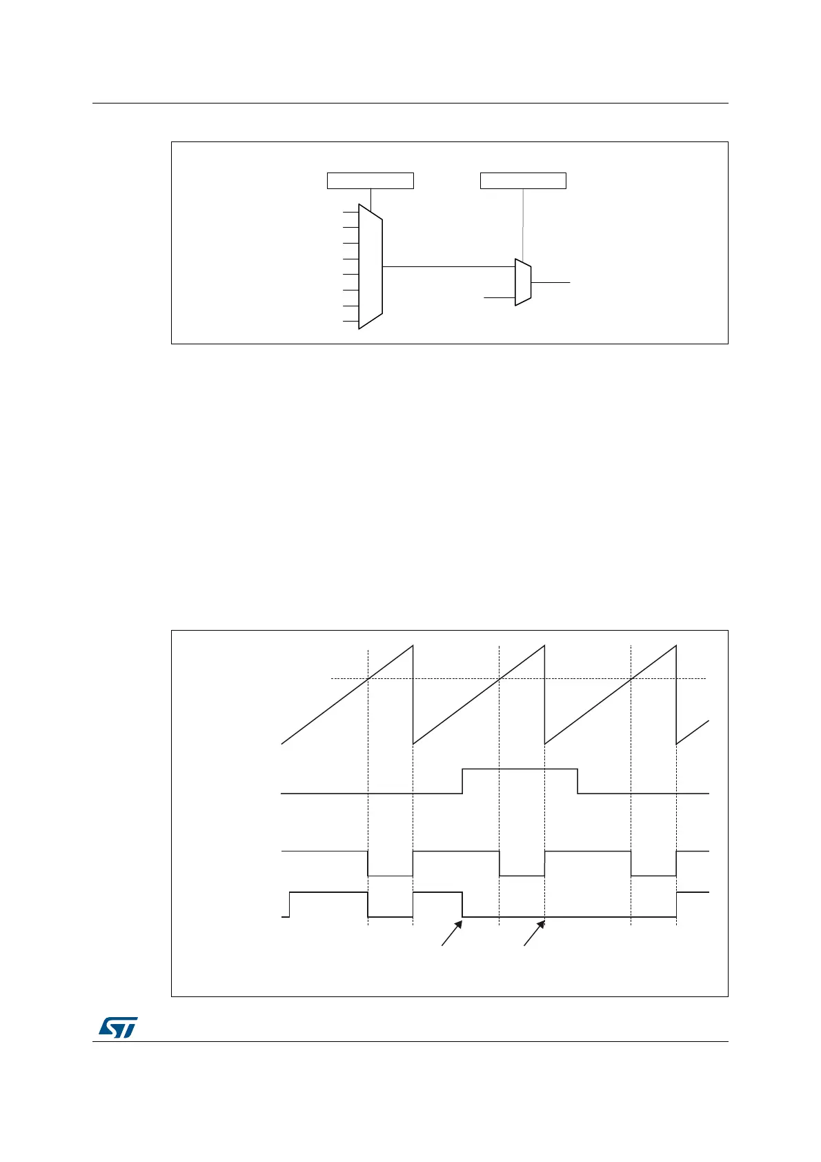
Figure 399 shows the behavior of the tim_ocxref signal when the tim_etrf input becomes
high, for both values of the OCxCE enable bit. In this example, the timer TIMx is
programmed in PWM mode.
Figure 399. Clearing TIMx tim_ocxref
MSv62341V1
OCRSEL[2:0] OCCS
tim_ocref_clr
TIMx_AF2
tim_ocref_clr8
tim_ocref_clr1
tim_ocref_clr2
tim_ocref_clr3
tim_ocref_clr4
tim_ocref_clr5
tim_ocref_clr6
tim_ocref_clr7
tim_etrf
tim_ocref_clr_int
TIMx_SMCR
MSv62342V1
(CCRx)
Counter (CNT)
tim_etrf
tim_ocxref
(OCxCE = ‘0’)
tim_ocxref
(OCxCE = ‘1’)
tim_ocref_clr_int
becomes high
tim_ocref_clr_int
still high
 Loading...


