General-purpose timers (TIM15/TIM16/TIM17) RM0440
1368/2126 RM0440 Rev 4
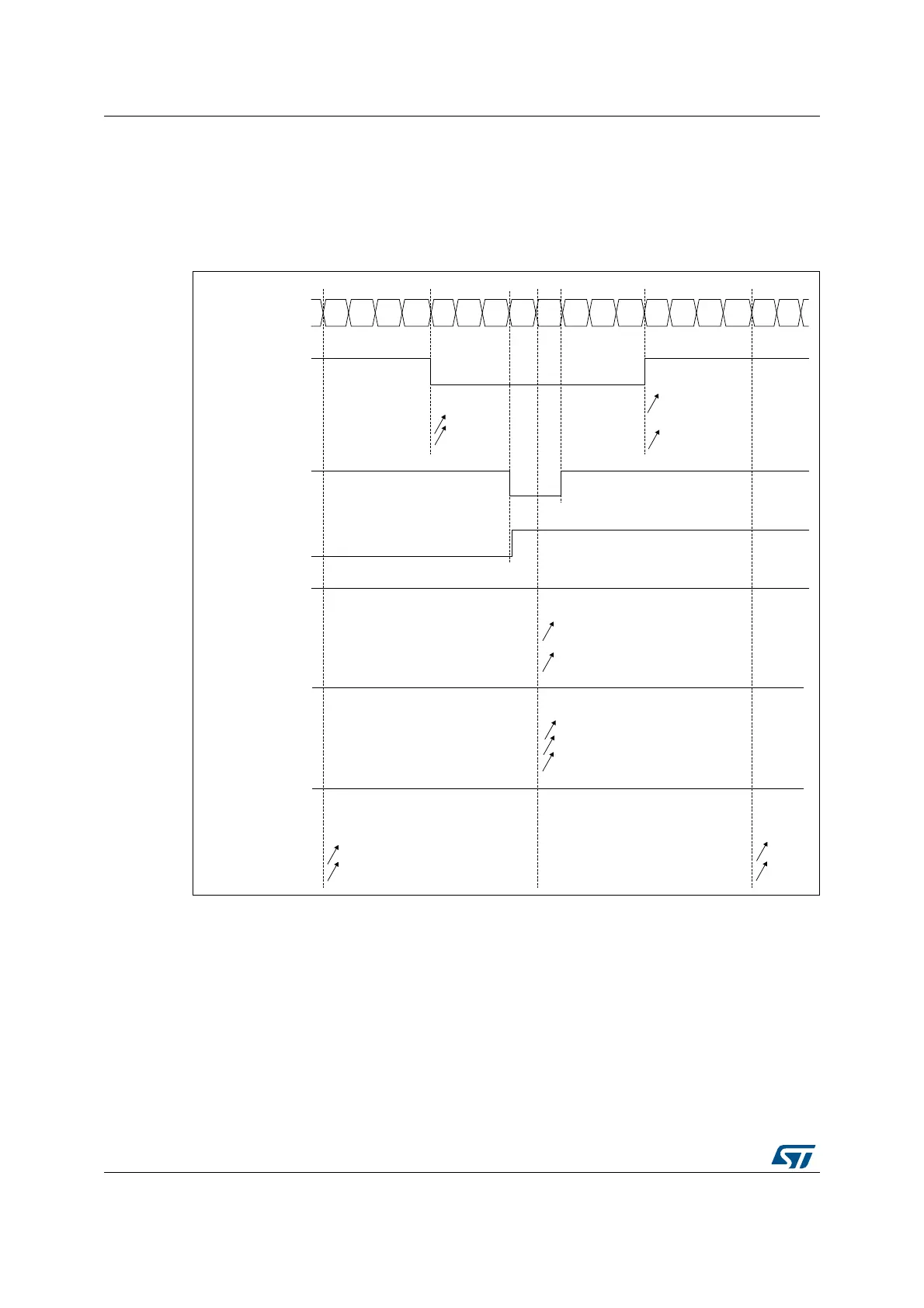
In the following example, we consider PWM mode 1. The reference PWM signal tim_ocxref
is high as long as TIMx_CNT < TIMx_CCRx else it becomes low. If the compare value in
TIMx_CCRx is greater than the auto-reload value (in TIMx_ARR) then tim_ocxref is held at
‘1’. If the compare value is 0 then tim_ocxref is held at ‘0’. Figure 459 shows some edge-
aligned PWM waveforms in an example where TIMx_ARR=8.
Figure 459. Edge-aligned PWM waveforms (ARR=8)
Dithering mode
The PWM mode effective resolution can be increased by enabling the dithering mode, using
the DITHEN bit in the TIMx_CR1 register. This applies to both the CCR (for duty cycle
resolution increase) and ARR (for PWM frequency resolution increase).
The operating principle is to have the actual CCR (or ARR) value slightly changed (adding
or not one timer clock period) over 16 consecutive PWM periods, with predefined patterns.
This allows a 16-fold resolution increase, considering the average duty cycle or PWM
period. The Figure 460 below presents the dithering principle applied to 4 consecutive PWM
cycles.
MSv62328V1
CCxIF
012345678765432 101
Counter register
CCRx = 4
tim_ocxref
CMS=01
CMS=10
CMS=11
CCxIF
CCRx=7
tim_ocxref
CMS=10 or 11
CCxIF
CCRx=8
tim_ocxref
CMS=01
CMS=10
CMS=11
‘1’
CCxIF
CCRx>8
tim_ocxref
CMS=01
CMS=10
CMS=11
‘1’
CCxIF
CCRx=0
tim_ocxref
CMS=01
CMS=10
CMS=11
‘0’
 Loading...


