Serial audio interface (SAI) RM0440
1810/2126 RM0440 Rev 4
counterpart is that the software has to perform some operations to de-interleave the data of
each microphone.
In the other hand, when the slot width is set to 8 bits, each data available into the SAI_ADR
will contain 8 useful bits. This increases the amount of words stored into the memory.
However, it offers the advantage to avoid extra processing since each word contains
information from one microphone.
SAI_ADR data format example
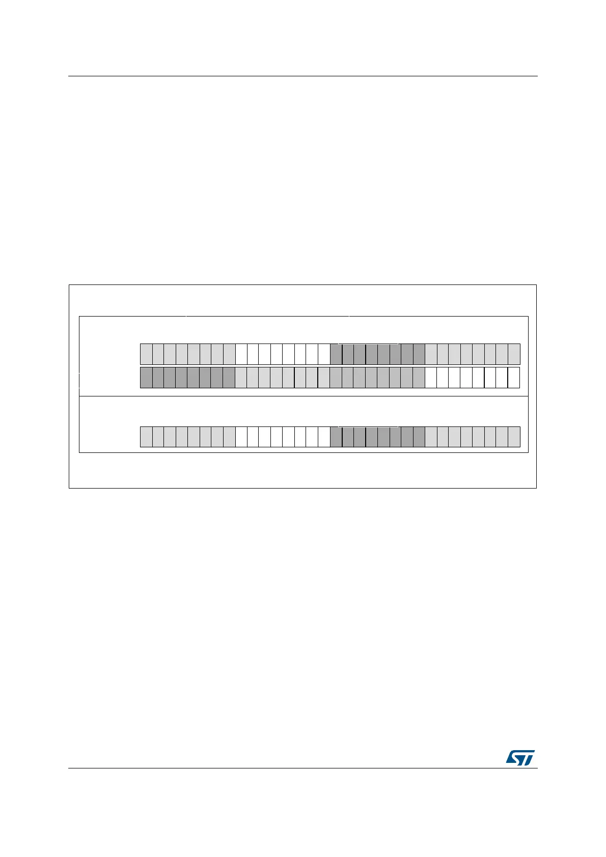
• 32-bit slot width (DS = 0b111 and SLOTSZ = 0). Refer to Figure 618.
For an 8 microphone configuration, two consecutive words read from the SAI_ADR
register contain a data byte from each microphone.
For a 4 microphones configuration, each word read from the SAI_ADR register
contains a data byte from each microphone.
Figure 618. SAI_ADR format in TDM, 32-bit slot width
• 16-bit slot width (DS = 0b100 and SLOTSZ = 0). Refer to Figure 619.
For an 8 microphone configuration, four consecutive words read from the SAI_ADR
register contain a data byte from each microphone. Note that the 16-bit data of
SAI_ADR are right aligned.
For 4 or 2 microphone configuration, the SAI behavior is similar to 8-microphone
configurations. Up to 2 words of 16 bits are required to acquire a byte from 4
microphones and a single word for 2 microphones.
MSv35470V1
M1L-1
M1L-2
M1L-3
M1L-4
M1R-1
M1R-2
M1R-3
M1R-4
M1L-5
M1L-6
M1L-7
M1L-8
M1R-5
M1R-6
M1R-7
M1R-8
M2L-1
M2L-2
M2L-3
M2L-4
M2L-5
M2L-6
M2L-7
M2L-8
M2R-1
M2R-2
M2R-3
M2R-4
M2R-5
M2R-6
M2R-7
M2R-8
b31 b0
M3L-1
M3L-2
M3L-3
M3L-4
M3L-5
M3L-6
M3L-7
M3L-8
M3R-1
M3R-2
M3R-3
M3R-4
M3R-5
M3R-6
M3R-7
M3R-8
M4L-1
M4L-2
M4L-3
M4L-4
M4L-5
M4L-6
M4L-7
M4L-8
M4R-1
M4R-2
M4R-3
M4R-4
M4R-5
M4R-6
M4R-7
M4R-8
LSBFIRST = 0
word 2n
word 2n+1
8 Microphones configuration
M1L-1
M1L-2
M1L-3
M1L-4
M1R-1
M1R-2
M1R-3
M1R-4
M1L-5
M1L-6
M1L-7
M1L-8
M1R-5
M1R-6
M1R-7
M1R-8
M2L-1
M2L-2
M2L-3
M2L-4
M2L-5
M2L-6
M2L-7
M2L-8
M2R-1
M2R-2
M2R-3
M2R-4
M2R-5
M2R-6
M2R-7
M2R-8
b31 b0
LSBFIRST = 0
word n
4 Microphones configuration
 Loading...


