Basic timers (TIM6/TIM7) RM0440
1458/2126 RM0440 Rev 4
31.3.8 Debug mode
When the microcontroller enters debug mode (Cortex®-M4 with FPU core halted), the TIMx
counter can either continue to work normally or be stopped.
The behavior in debug mode can be programmed with a dedicated configuration bit per
timer in the Debug support (DBG) module.
For more details, refer to section Debug support (DBG).
31.3.9 TIM6/TIM7 low-power modes
31.3.10 TIM6/TIM7 interrupts
The TIM6/TIM7 can generate a single interrupt, as shown in Table 307.
31.4 TIM6/TIM7 registers
Refer to Section 1.2 on page 72 for a list of abbreviations used in register descriptions.
The peripheral registers can be accessed by half-words (16-bit) or words (32-bit).
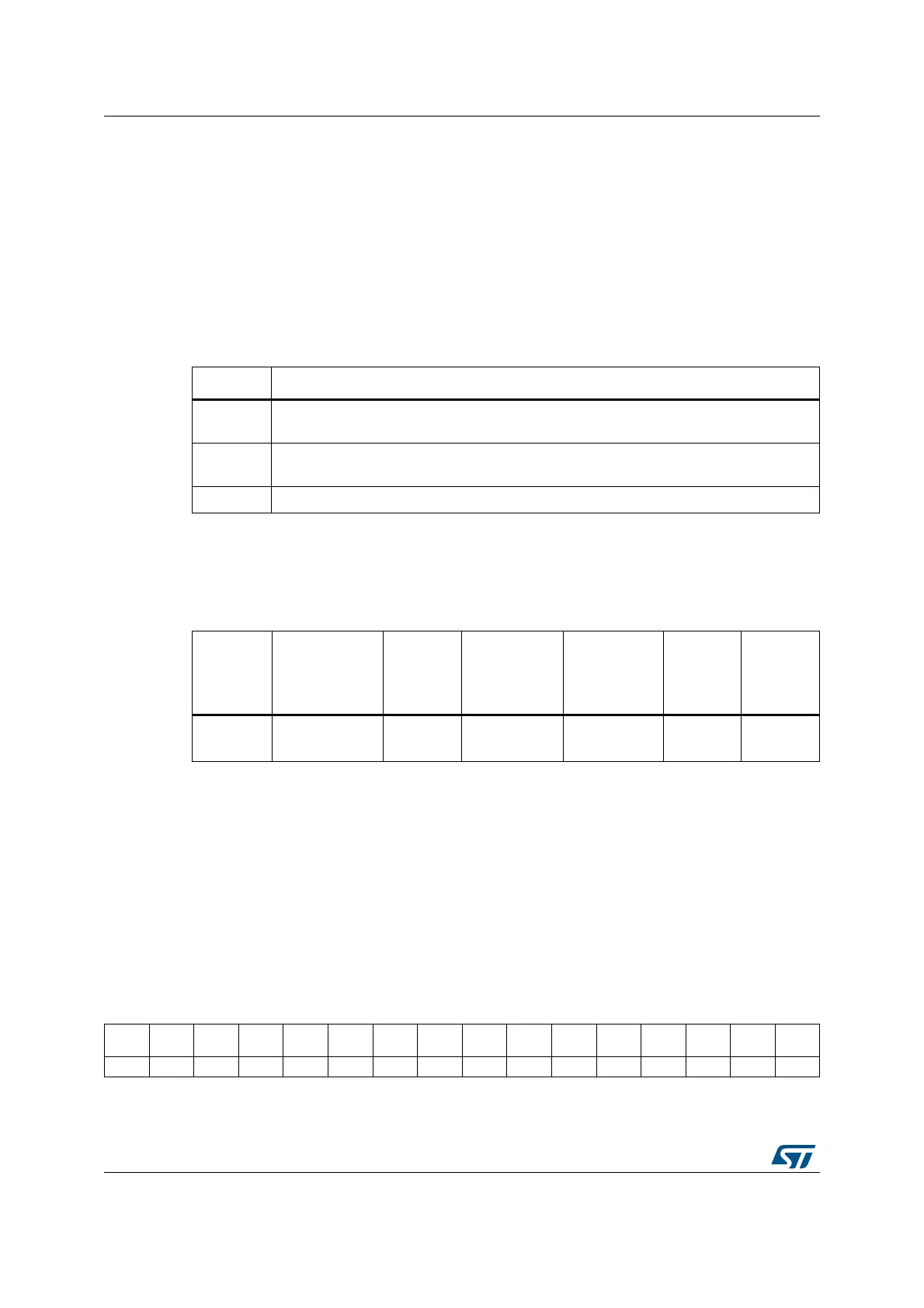
31.4.1 TIMx control register 1 (TIMx_CR1)(x = 6 to 7)
Address offset: 0x00
Reset value: 0x0000
Table 306. Effect of low-power modes on TIM6/TIM7
Mode Description
Sleep
No effect, peripheral is active. The interrupts can cause the device to exit from Sleep
mode.
Stop
The timer operation is stopped and the register content is kept. No interrupt can be
generated.
Standby The timer is powered-down and must be reinitialized after exiting the Standby mode.
Table 307. Interrupt request
Interrupt
acronym
Interrupt event Event flag
Enable
control bit
Interrupt
clear method
Exit from
Sleep
mode
Exit from
Stop and
Standby
mode
TIM6
TIM7
Update UIF UIE write 0 in UIF Yes No
1514131211109876543210
Res. Res. Res.
DITH
EN
UIFRE
MAP
Res. Res. Res. ARPE Res. Res. Res. OPM URS UDIS CEN
rw rw rw rw rw rw rw
 Loading...


