AES hardware accelerator (AES) RM0440
1510/2126 RM0440 Rev 4
GCM processing
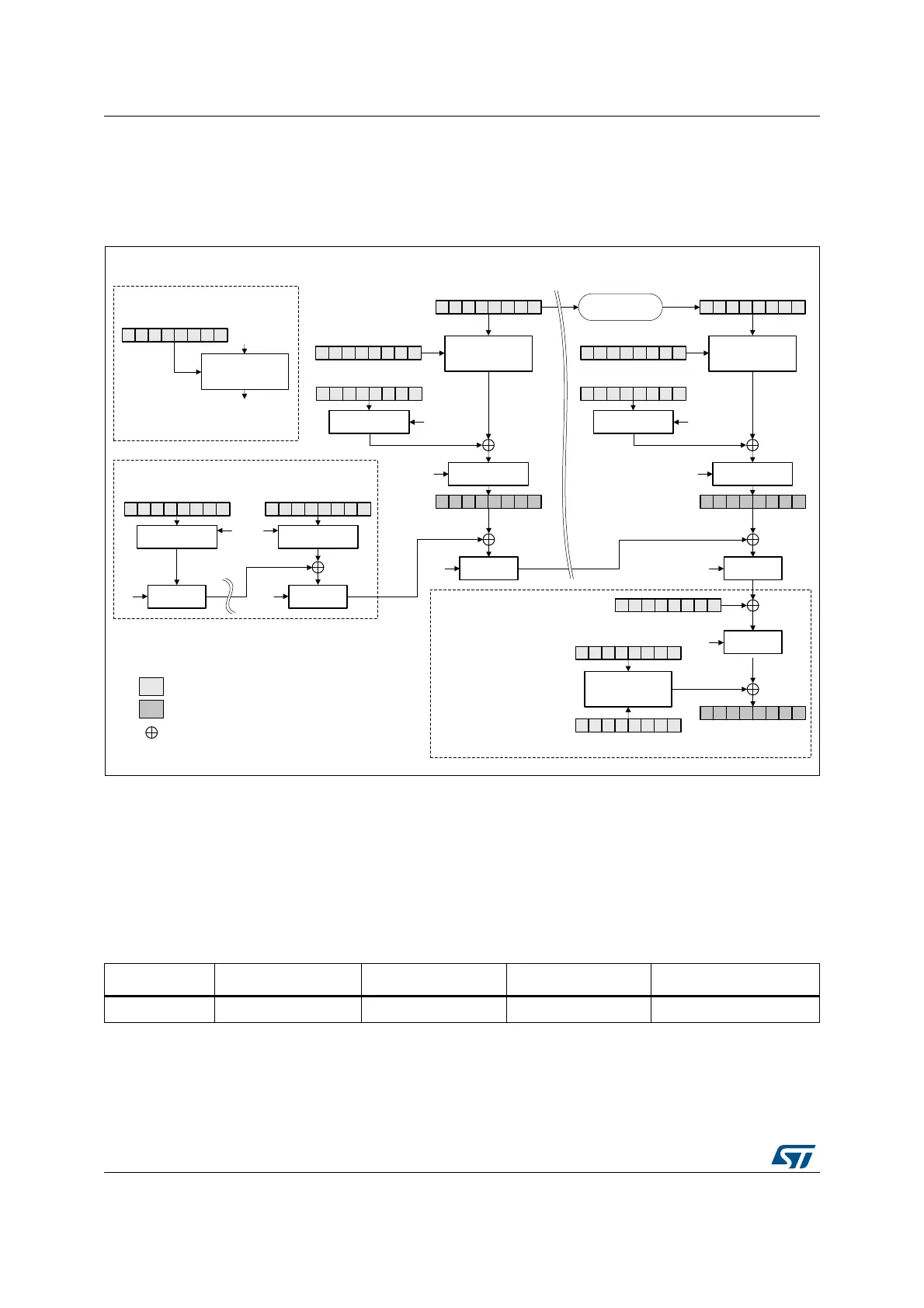
Figure 520 describes the GCM implementation in the AES peripheral. The GCM is selected
by writing 011 to the CHMOD[2:0] bitfield of the AES_CR register.
Figure 520. GCM authenticated encryption
The mechanism for the confidentiality of the plaintext in GCM mode is similar to that in the
Counter mode, with a particular increment function (denoted 32-bit increment) that
generates the sequence of input counter blocks.
AES_IVRx registers keeping the counter block of data are used for processing each data
block. The AES peripheral automatically increments the Counter[31:0] bitfield. The first
counter block (CB1) is derived from the initial counter block ICB by the application software
(see Table 321).
MSv42149V1
(4) Final
(1) Init
(2) Header
AES_KEYRx (KEY)
AES_DINR (plaintext P1)
AES_DOUTR
(ciphertext C1)
DATATYPE
[1:0]
Swap
management
AES_IVRx
ICB + (32-bit counter = 0x02)
input
output
Legend
XOR
Swap
management
DATATYPE
[1:0]
AES_KEYRx (KEY)
DATATYPE[1:0]
Swap
management
AES_IVRx
Swap
management
DATATYPE
[1:0]
Counter
increment (+1)
AES_DINR (plaintext Pn)
H
AES_DOUTR
(ciphertext Cn)
H
Encrypt
[0]
128
H
AES_DINR (AAD 0)
Swap
management
Swap
management
AES_DINR (AAD i)
GF2mul
DATATYPE
[1:0]
GF2mul
H
H
AES_KEYRx (KEY)
GF2mul GF2mul
GF2mul
H
AES_DINR
Len(A)
64
|| Len(C)
64
Encrypt
AES_KEYRx (key)
AES_IVRx
(IV + 32-bit counter (= 0x0))
AES_DOUTR
(Authentication TAG T)
S
Encrypt Encrypt
Block 1 Block n
CBn
CB1 CBn
(3) Payload
Table 321. GCM mode IVI bitfield initialization
Register AES_IVR3[31:0] AES_IVR2[31:0] AES_IVR1[31:0] AES_IVR0[31:0]
Input data ICB[31:0] ICB[63:32] ICB[95:64] Counter[31:0] = 0x2
Note: In this mode, the settings 01 and 11 of the MODE[1:0] bitfield are forbidden.
 Loading...


