High-resolution timer (HRTIM) RM0440
930/2126 RM0440 Rev 4
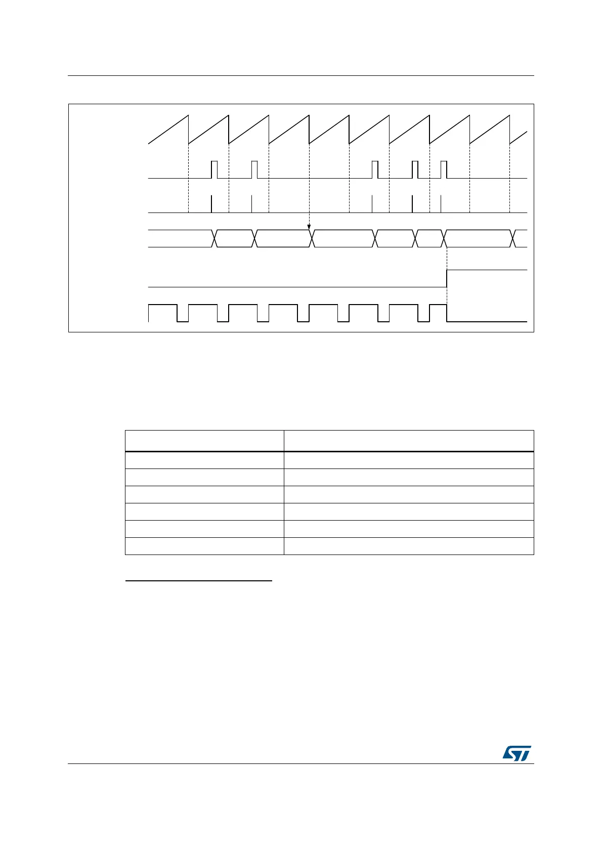
Figure 246. Fault counter cumulative mode (FLTxRSTM = 1, FLTxCNT[3:0] = 2)
A given FLTx input counter can be reset by a single source. The Table 236 indicates which
timer unit associated with a given fault. This does not prevent to have a fault line shared by
multiple timer (e.g. FLT1 with event counter enabled, acting on timer A, timer B and timer C
simultaneously).
System fault input (hrtim_sys_flt)
This fault is provided by the MCU Class B circuitry (see the system configuration controller
(SYSCFG) section for details) and corresponds to a system fault coming from:
• the clock security system
• the SRAM parity checker
• the Cortex
®
-M4 with FPU lockup signal
• the PVD detector
• the Flash ECC double error detection
This input overrides the FAULT inputs and disables all outputs having FAULTy[1:0] = 01, 10,
11.
MSv47426V1
0 032101 2
PWM output
FLT event
FLT counter
FLT edge detector
FLT input
Counter
Table 236. Fault 1..6 counter reset source
Fault Input Fault counter reset source
hrtim_flt1[4:1] Timer A reset/roll-over
hrtim_flt2[4:1] Timer B reset/roll-over
hrtim_flt3[4:1] Timer C reset/roll-over
hrtim_flt4[4:1] Timer D reset/roll-over
hrtim_flt5[4:1] Timer E reset/roll-over
hrtim_flt6[4:1] Timer F reset/roll-over