RM0440 Rev 4 633/2126
RM0440 Analog-to-digital converters (ADC)
724
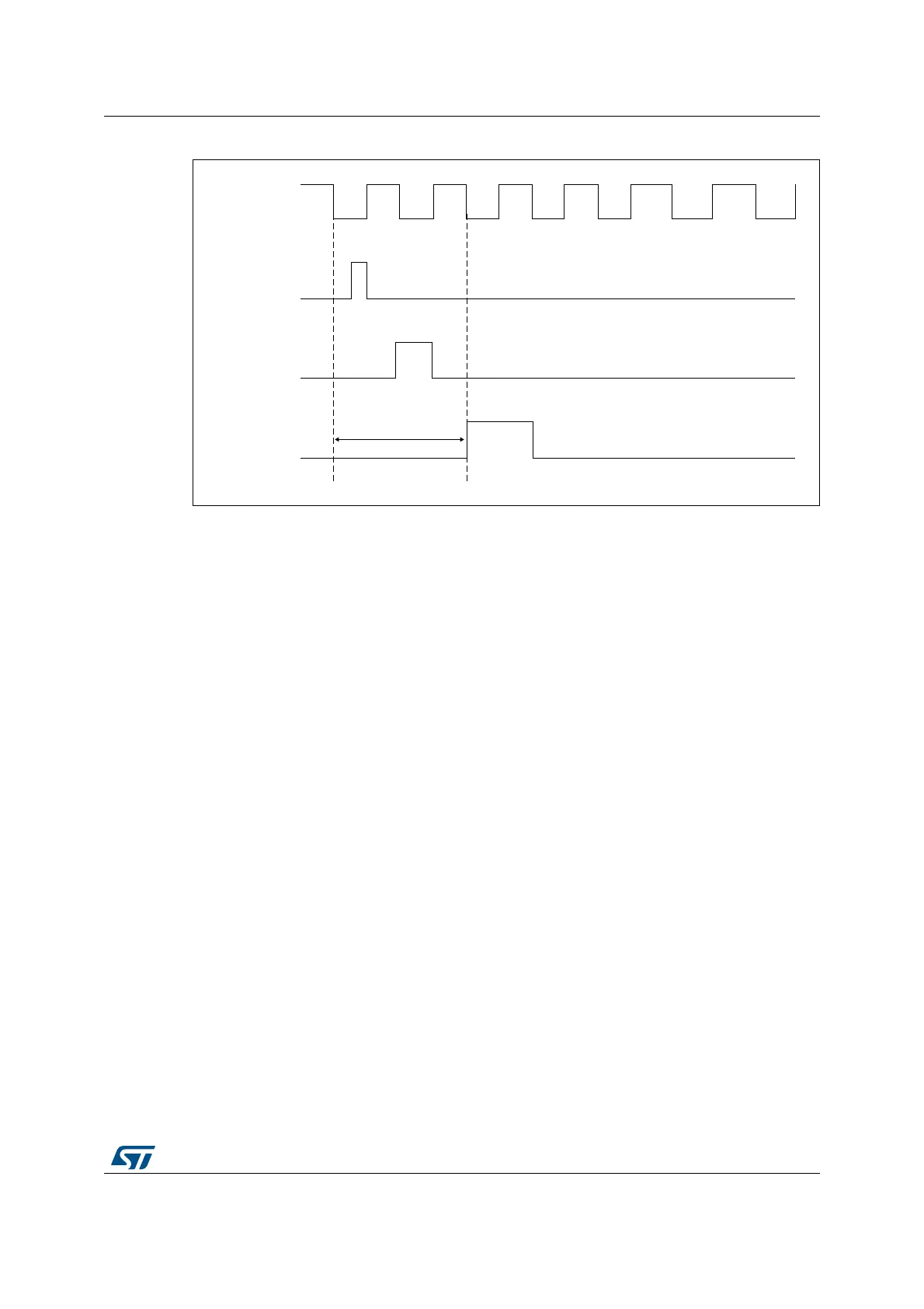
Figure 98. Injected conversion latency
1. The maximum latency value can be found in the electrical characteristics of the device datasheet.
21.4.20 Discontinuous mode (DISCEN, DISCNUM, JDISCEN)
Regular group mode
This mode is enabled by setting the DISCEN bit in the ADC_CFGR register.
It is used to convert a short sequence (subgroup) of n conversions (n ≤ 8) that is part of the
sequence of conversions selected in the ADC_SQRy registers. The value of n is specified
by writing to the DISCNUM[2:0] bits in the ADC_CFGR register.
When an external trigger occurs, it starts the next n conversions selected in the ADC_SQRy
registers until all the conversions in the sequence are done. The total sequence length is
defined by the L[3:0] bits in the ADC_SQR1 register.
Example:
• DISCEN=1, n=3, channels to be converted = 1, 2, 3, 6, 7, 8, 9, 10, 11
– 1st trigger: channels converted are 1, 2, 3 (an EOC event is generated at each
conversion).
– 2nd trigger: channels converted are 6, 7, 8 (an EOC event is generated at each
conversion).
– 3rd trigger: channels converted are 9, 10, 11 (an EOC event is generated at each
conversion) and an EOS event is generated after the conversion of channel 11.
– 4th trigger: channels converted are 1, 2, 3 (an EOC event is generated at each
conversion).
–...
• DISCEN=0, channels to be converted = 1, 2, 3, 6, 7, 8, 9, 10,11
– 1st trigger: the complete sequence is converted: channel 1, then 2, 3, 6, 7, 8, 9, 10
and 11. Each conversion generates an EOC event and the last one also generates
an EOS event.
– All the next trigger events will relaunch the complete sequence.
MSv43771V1
adc_ker_ck
(1)
Injection event
Reset ADC
SOC
max. latency