RM0440 Rev 4 1469/2126
RM0440 Low-power timer (LPTIM)
1487
The external triggers are considered asynchronous signals for the LPTIM. So after a trigger
detection, a two-counter-clock period latency is needed before the timer starts running due
to the synchronization.
If a new trigger event occurs when the timer is already started it will be ignored (unless
timeout function is enabled).
Note: The timer must be enabled before setting the SNGSTRT/CNTSTRT bits. Any write on these
bits when the timer is disabled will be discarded by hardware.
32.4.7 Operating mode
The LPTIM features two operating modes:
• The Continuous mode: the timer is free running, the timer is started from a trigger event
and never stops until the timer is disabled
• One-shot mode: the timer is started from a trigger event and stops when reaching the
ARR value.
One-shot mode
To enable the one-shot counting, the SNGSTRT bit must be set.
A new trigger event will re-start the timer. Any trigger event occurring after the counter starts
and before the counter reaches ARR will be discarded.
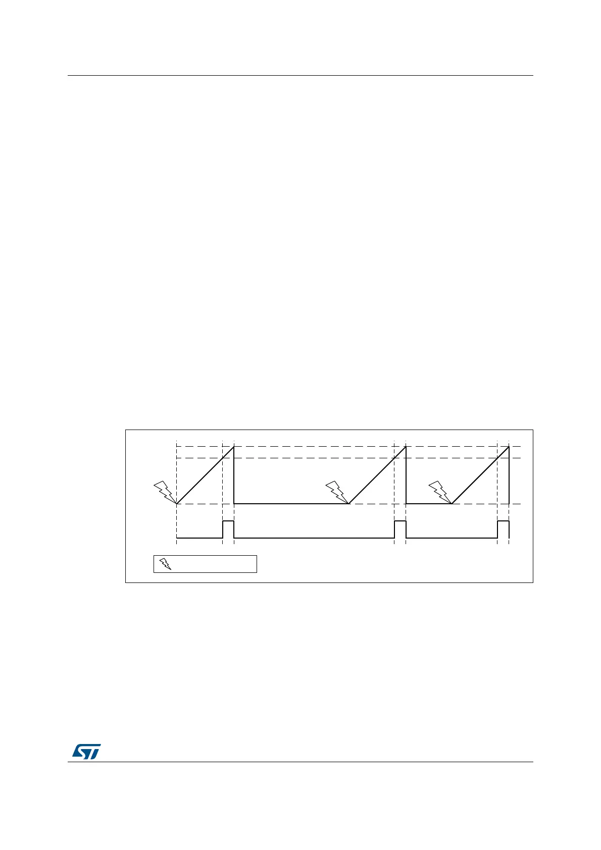
In case an external trigger is selected, each external trigger event arriving after the
SNGSTRT bit is set, and after the counter register has stopped (contains zero value), will
start the counter for a new one-shot counting cycle as shown in Figure 495.
Figure 495. LPTIM output waveform, single counting mode configuration
- Set-once mode activated:
It should be noted that when the WAVE bit-field in the LPTIM_CFGR register is set, the Set-
once mode is activated. In this case, the counter is only started once following the first
trigger, and any subsequent trigger event is discarded as shown in Figure 496.
MSv39230V2
PWM
0
Compare
LPTIM_ARR
External trigger event
 Loading...


