Advanced-control timers (TIM1/TIM8/TIM20) RM0440
1150/2126 RM0440 Rev 4
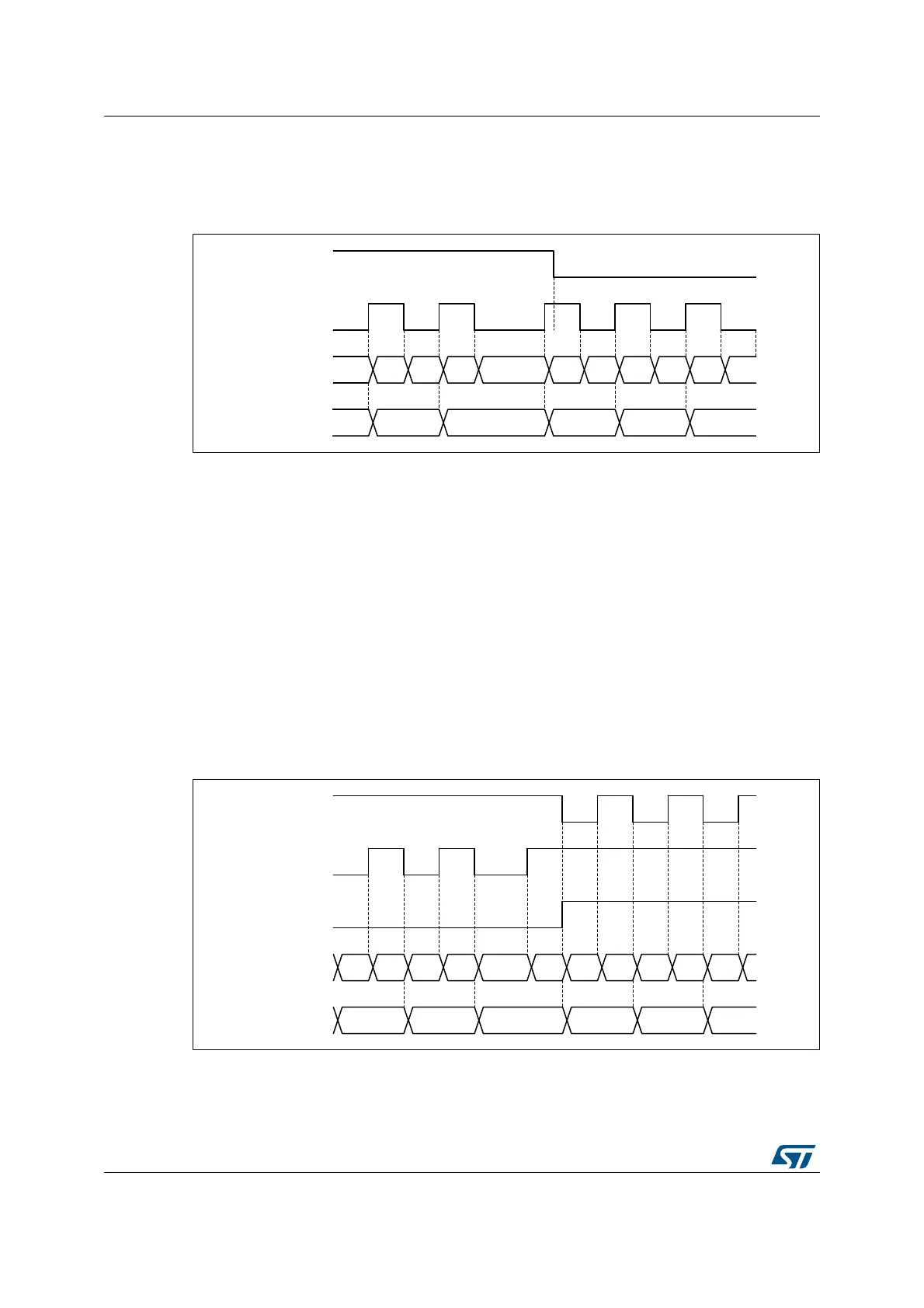
The polarity of the direction signal on tim_ti1 is set with the CC1P bit: 0 corresponds to
positive polarity (up-counting when tim_ti1 is high and down-counting when tim_ti1 is low)
and CC1P = 1 corresponds to negative polarity (up-counting when tim_ti1 is low).
Figure 332. Direction plus clock encoder mode
Directional Clock encoder mode
In the “directional clock” mode on Figure 333, the clocks are provided on two lines, with a
single one at once, depending on the direction, so as to have one up-counting clock line and
one down-counting clock line.
This mode is enabled with the SMS[3:0] bitfield in the TIMx_SMCR register, as following:
• 1100: x2 mode, the counter is updated on both rising and falling edges of any of the two
clock line. The CC1P and CC2P bits are coding for the clock idle state. CCxP = 0
corresponds to high-level idle state (refer to Figure 333 below) and CCxP = 1
corresponds to low-level idle state (refer to Figure 334 below).
• 1101: x1 mode, the counter is updated on a single clock edge, as per CC1P and CC2P
bit value. CCxP = 0 corresponds to falling edge sensitivity and high-level idle state
(refer to Figure 333 below), CCxP = 1 corresponds to rising edge sensitivity and low-
level idle state (refer to Figure 334 below).
Figure 333. Directional clock encoder mode (CC1P = CC2P = 0)
MSv62352V1
tim_ti1
Counter x2 mode
tim_ti2
Counter x1 mode
7 9 8
7
6 8
68 9 10 11 10 9 8 776
MSv62353V1
DIR bit
Counter x2 mode
Counter x1 mode
7 7 6
58 9 11 10 9 8 77 10
8
6 6
tim_ti2
tim_ti1
6 5
 Loading...


