RM0440 Rev 4 753/2126
RM0440 Digital-to-analog converter (DAC)
773
22.7 DAC registers
Refer to Section 1 on page 72 for a list of abbreviations used in register descriptions.
The peripheral registers have to be accessed by words (32-bit).
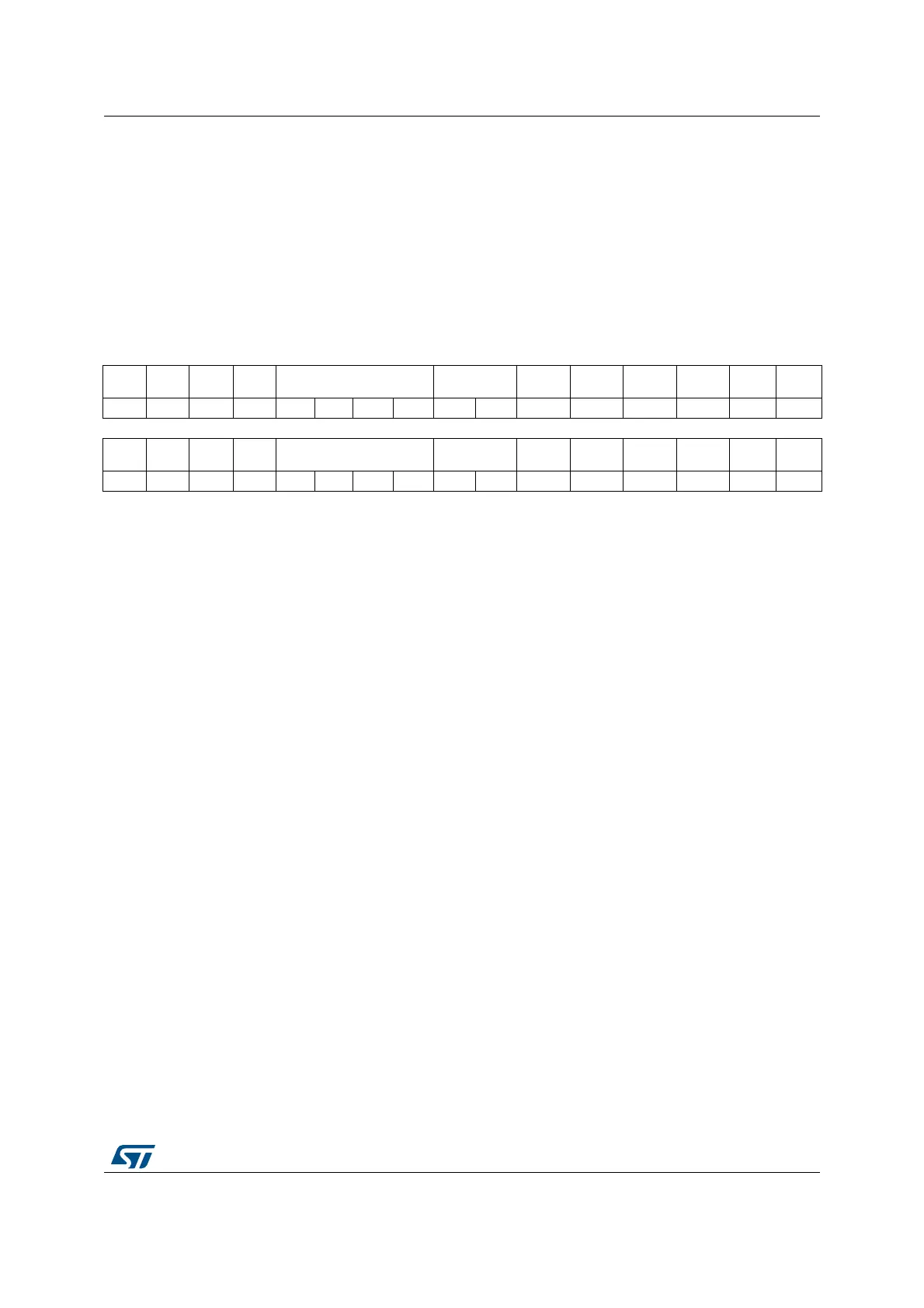
22.7.1 DAC control register (DAC_CR)
Address offset: 0x00
Reset value: 0x0000 0000
31 30 29 28 27 26 25 24 23 22 21 20 19 18 17 16
Res. CEN2
DMAU
DRIE2
DMAE
N2
MAMP2[3:0] WAVE2[1:0] TSEL2[3] TSEL2[2] TSEL2[1] TSEL2[0] TEN2 EN2
rw rw rw rw rw rw rw rw rw rw rw rw rw rw rw
15 14 13 12 11 10 9 8 7 6 5 4 3 2 1 0
Res. CEN1
DMAU
DRIE1
DMAE
N1
MAMP1[3:0] WAVE1[1:0] TSEL1[3] TSEL1[2] TSEL1[1] TSEL1[0] TEN1 EN1
rw rw rw rw rw rw rw rw rw rw rw rw rw rw rw
Bit 31 Reserved, must be kept at reset value.
Bit 30 CEN2: DAC channel2 calibration enable
This bit is set and cleared by software to enable/disable DAC channel2 calibration, it can be
written only if EN2 bit is set to 0 into DAC_CR (the calibration mode can be entered/exit only
when the DAC channel is disabled) Otherwise, the write operation is ignored.
0: DAC channel2 in Normal operating mode
1: DAC channel2 in calibration mode
Note: This bit is available only on dual-channel DACs. Refer to Section 22.3: DAC
implementation.
Bit 29 DMAUDRIE2: DAC channel2 DMA underrun interrupt enable
This bit is set and cleared by software.
0: DAC channel2 DMA underrun interrupt disabled
1: DAC channel2 DMA underrun interrupt enabled
Note: This bit is available only on dual-channel DACs. Refer to Section 22.3: DAC
implementation.
Bit 28 DMAEN2: DAC channel2 DMA enable
This bit is set and cleared by software.
0: DAC channel2 DMA mode disabled
1: DAC channel2 DMA mode enabled
Note: This bit is available only on dual-channel DACs. Refer to Section 22.3: DAC
implementation.
 Loading...


