EasyManua.ls Logo

ST STM32H7 Series User Manual

ST STM32H7 Series
262 pages
To Next Page IconTo Next Page
To Previous Page IconTo Previous Page
Page #19 background imageLoading...
Page #19 background image
PM0214 Rev 9 19/262
PM0214 The Cortex-M4 processor
261
General-purpose registers
R0-R12 are 32-bit general-purpose registers for data operations.
Stack pointer
The Stack Pointer (SP) is register R13. In Thread mode, bit[1] of the CONTROL register
indicates the stack pointer to use:
• 0: Main Stack Pointer (MSP). This is the reset value.
• 1: Process Stack Pointer (PSP).
On reset, the processor loads the MSP with the value from address 0x00000000.
Link register
The Link Register (LR) is register R14. It stores the return information for subroutines,
function calls, and exceptions. On reset, the processor loads the LR value 0xFFFFFFFF.
Program counter
The Program Counter (PC) is register R15. It contains the current program address. On
reset, the processor loads the PC with the value of the reset vector, which is at address
0x00000004. Bit[0] of the value is loaded into the EPSR T-bit at reset and must be 1.
Program status register
The Program Status Register (PSR) combines:
• Application Program Status Register (APSR)
• Interrupt Program Status Register (IPSR)
• Execution Program Status Register (EPSR)
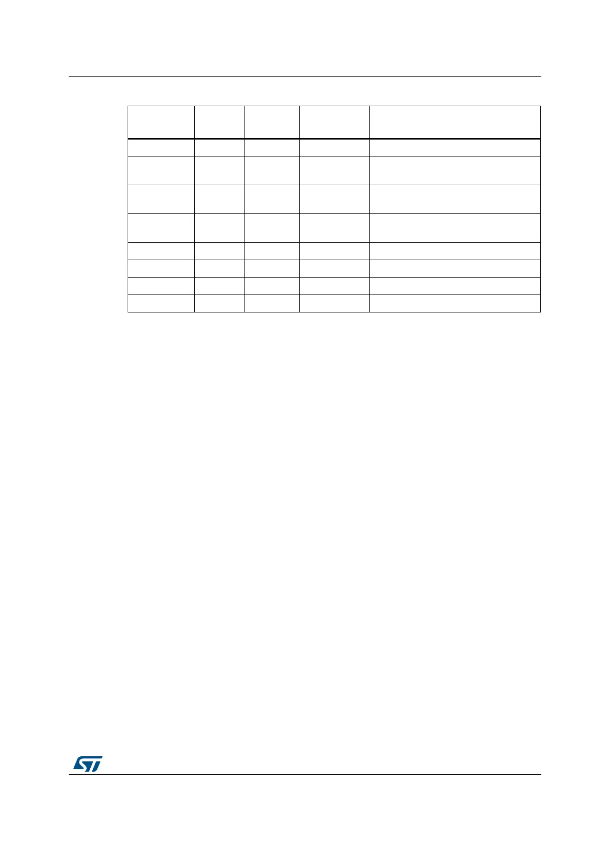
PSR read-write Privileged 0x01000000 Program status register on page 19
ASPR read-write Either Unknown
Application program status register on
page 21
IPSR read-only Privileged 0x00000000
Interrupt program status register on
page 22
EPSR read-only Privileged 0x01000000
Execution program status register on
page 22
PRIMASK read-write Privileged 0x00000000 Priority mask register on page 24
FAULTMASK read-write Privileged 0x00000000 Fault mask register on page 24
BASEPRI read-write Privileged 0x00000000 Base priority mask register on page 25
CONTROL read-write Privileged 0x00000000 CONTROL register on page 25
1. Describes access type during program execution in thread mode and Handler mode. Debug access can
differ.
2. An entry of either means privileged and unprivileged software can access the register.
Table 3. Core register set summary (continued)
Name Type
(1)
Required
privilege
(2)
Reset
value
Description

Table of Contents

Other manuals for ST STM32H7 Series

Question and Answer IconNeed help?

Do you have a question about the ST STM32H7 Series and is the answer not in the manual?

ST STM32H7 Series Specifications

General IconGeneral
BrandST
ModelSTM32H7 Series
CategoryComputer Hardware
LanguageEnglish

Summary

About this document

Typographical Conventions

Defines formatting used in the document for clarity.

List of Abbreviations for Registers

Provides a list of abbreviations used in register descriptions for quick reference.

STM32 Cortex-M4 Processor Overview

Introduces the STM32 Cortex-M4 processor's architecture and key features.

The Cortex-M4 Processor

Programmer's Model

Describes registers, modes, and privilege levels for software execution.

Memory Model

Details the processor's memory map, access behavior, and bit-banding features.

Exception Model

Explains exception states, types, priorities, and handling mechanisms.

Fault Handling

Covers fault types, escalation, status registers, and lockup conditions.

Power Management

Describes mechanisms for entering and exiting low-power sleep modes.

The STM32 Cortex-M4 Instruction Set

Instruction Set Summary

Lists supported Cortex-M4 instructions and their organization.

Memory Access Instructions

Details instructions for loading and storing data from/to memory.

General Data Processing Instructions

Explains instructions for arithmetic, logical, and data manipulation.

Multiply and Divide Instructions

Describes instructions for multiplication and division operations.

Floating-Point Instructions

Details instructions for FPU operations, including VFPv4-SP extension.

Miscellaneous Instructions

Covers instructions like breakpoints, barriers, and supervisor calls.

Core Peripherals

About the STM32 Cortex-M4 Core Peripherals

Introduces the core peripherals accessible via the Private Peripheral Bus (PPB).

Memory Protection Unit (MPU)

Explains the MPU for memory region definition and access control.

Nested Vectored Interrupt Controller (NVIC)

Describes the NVIC for managing interrupts and exceptions with priority levels.

System Control Block (SCB)

Details registers for system control, configuration, and exception reporting.

SysTick Timer (STK)

Explains the 24-bit SysTick timer for system timing and RTOS ticks.

Floating Point Unit (FPU)

Describes the FPU for single-precision floating-point operations.

Revision History

Related product manuals