102 MS 441, MS 441 C
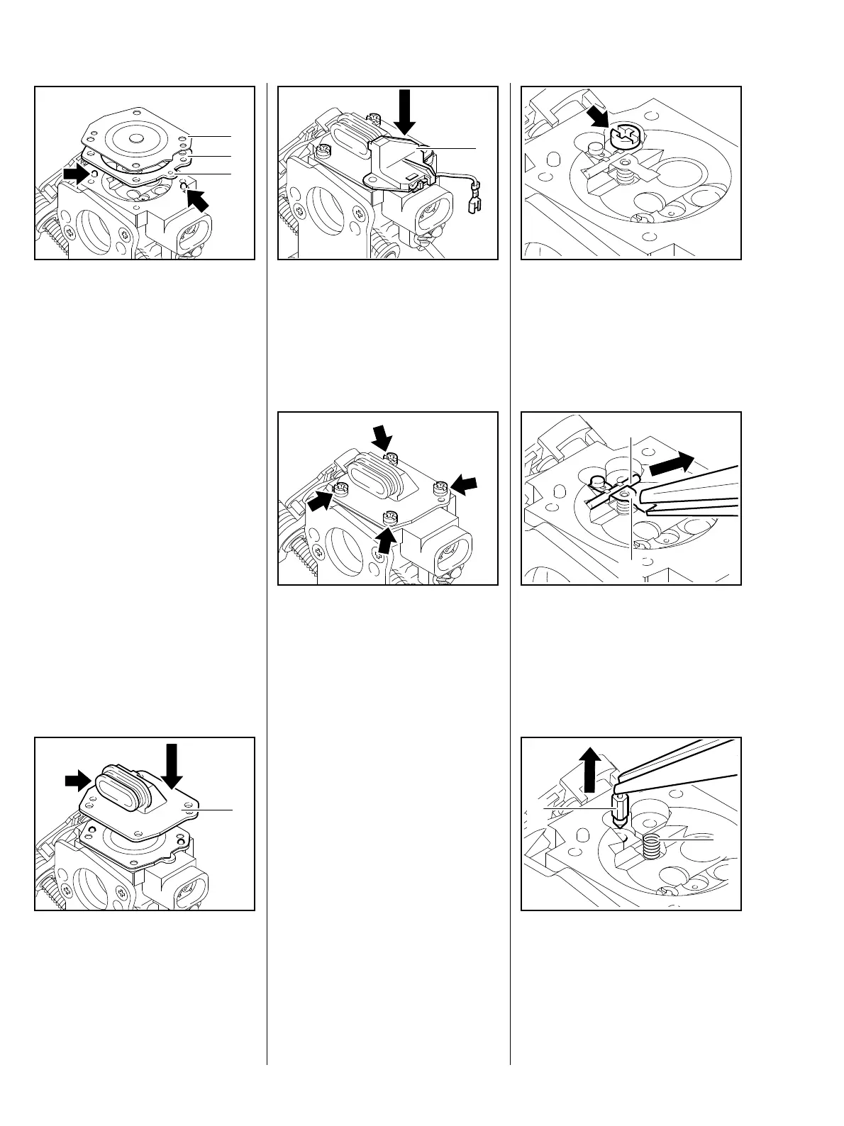
– Note installation sequence for
metering diaphragm (2) and
gasket (1).
: Position gasket (1) and metering
diaphragm (2) in the pegs
(arrows), ensuring that the tab (3)
faces towards the adjusting
219RA214 TG
3
2
1
screws.
: Position cover (1) so that the
connector (arrow) faces towards
the choke shutter and is secured
by the pegs.
219RA212 TG
1
Machines with handle heating
: Fit switch (1).
219RA216 TG
1
: Insert screws (arrows) and
tighten them down.
– Check that diaphragm and
gasket are correctly seated, then
tighten screws cross-wise.
– Reassemble all other parts in the
219RA210 TG
reverse sequence.
– Remove metering diaphragm,
b 14.4.2.
: Take out screw (arrow).
219RA218 TG
: Pull inlet control lever (1) with
spindle (2) out of the groove in
the inlet needle.
The spring under the inlet control
lever may pop out.
219RA219 TG
2
1
: Pull out inlet needle (1).
– Remove and examine spring (2),
replace if necessary.
219RA220 TG
2
1
14.4.3 Inlet needle