89MS 441, MS 441 C
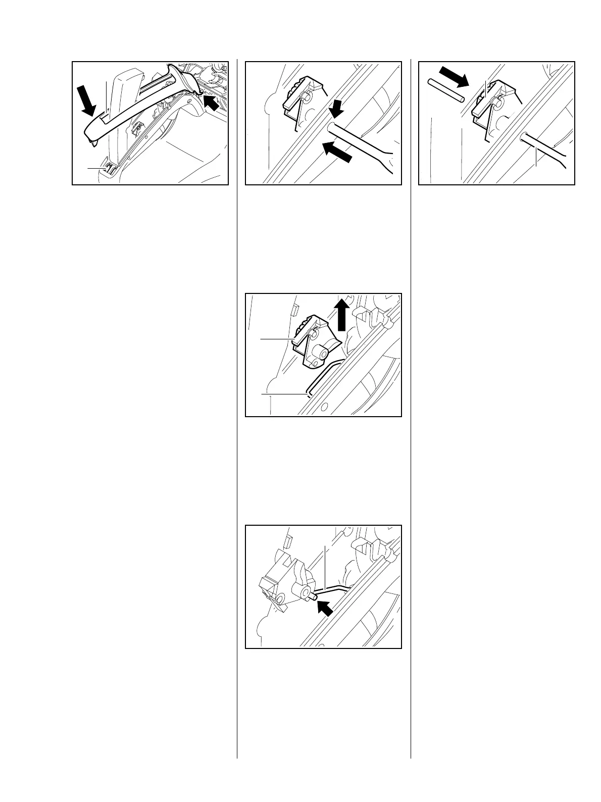
– Attach handle moulding (1)
(arrow).
: Fit handle moulding (1) over the
trigger interlock and press the
pegs into the mounts (2) until
they engage.
1
219RA447 TG
2
– Check correct operation again.
– Reassemble all other parts in the
reverse sequence.
– Tightening torques, b 3.5.
– Remove handle moulding,
b 12.3.
: Drive out pin (arrow) with
a punch.
219RA443 TG
: Disconnect brake cable (2).
: Take out switch lever (1).
– Examine switch lever (1), replace
if necessary.
219RA448 TG
1
2
: Hook brake cable (1) into hole
(arrow) in switch lever.
– Align switch lever.
219RA449 TG
1
: Centre switch lever (1) with
punch (2).
– Drive in the pin until it is
equidistant on both sides.
– Reassemble in the reverse
sequence.
219RA450 TG
1
2
– Tightening torques, b 3.5.
– Check correct operation.
12.3.1 Switch lever