85MS 441, MS 441 C
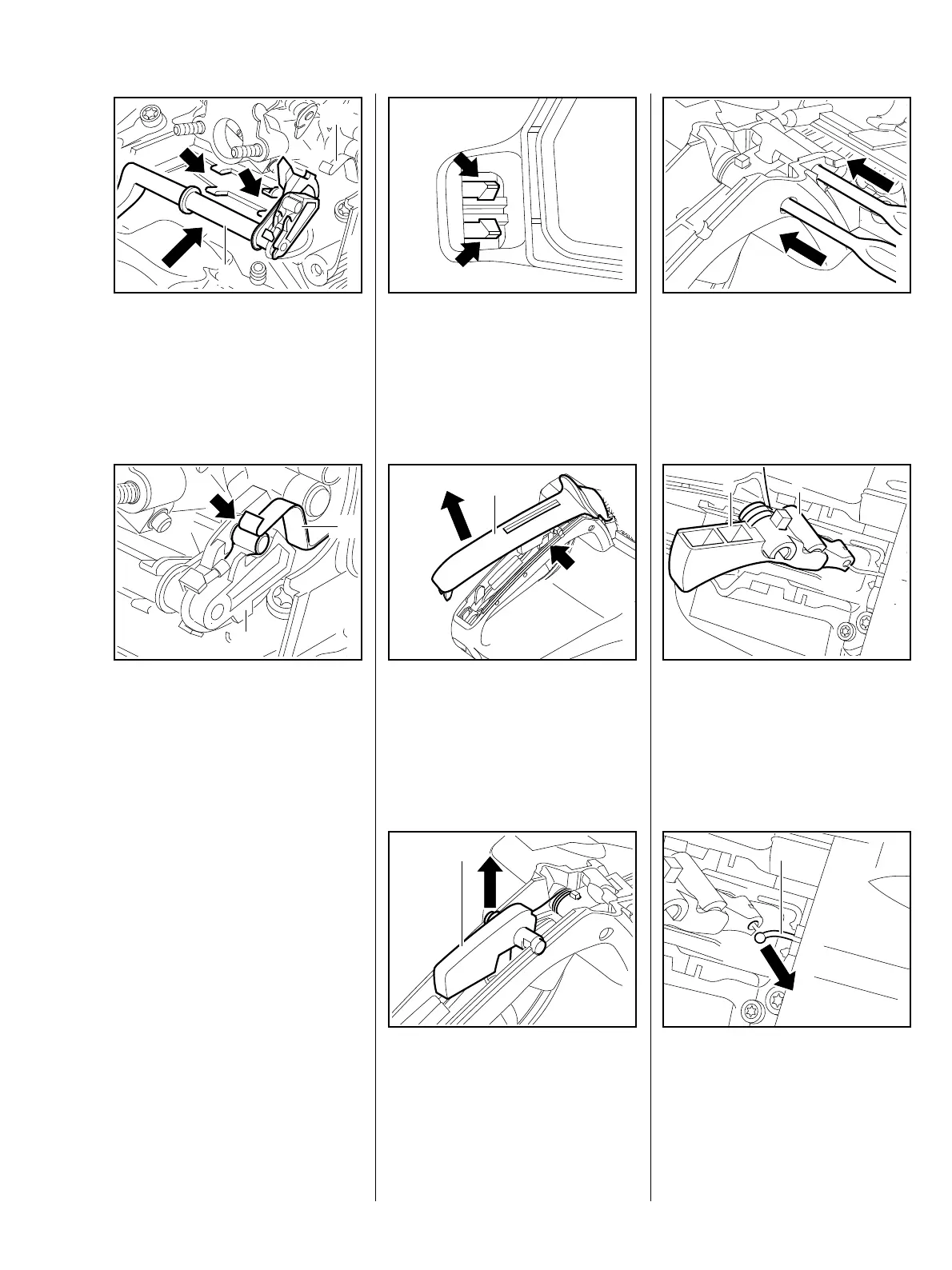
– Lift contact spring (1).
: Push switch shaft (2) into the
bearing guides (arrows) until it
engages.
1
2
219RA340 TG
– Contact spring (1) must engage
the guide of the switch shaft (2).
: Contact must be made between
short circuit wire and contact
spring (arrow) in switch position
"$".
1
2
219RA341 TG
– Install filter base, b 14.1.2.
– Install wiring to heating element
in machines with handle heating,
b 15.1.
– Check correct operation.
– Reassemble all other parts in the
reverse sequence.
– Tightening torques, b 3.5.
– Remove spacer flange,
b 14.2.
: Push pegs (arrows) apart and
through the tank housing.
: Remove handle moulding (1).
The trigger interlock (arrow) may
pop out.
1
219RA343 TG
: Remove throttle trigger
interlock (1).
1
219RA344 TG
The drag lever is located in the
throttle trigger and must therefore
also be removed.
: Drive pins (arrows) out with
apunch.
219RA345 TG
: Lift and turn throttle trigger (1)
with lever (2).
219RA346 TG
21
: Disconnect throttle cable (1).
– Remove throttle trigger and lever.
219RA347 TG
1
12.2 Throttle trigger/ throttle
trigger interlock