84 MS 441, MS 441 C
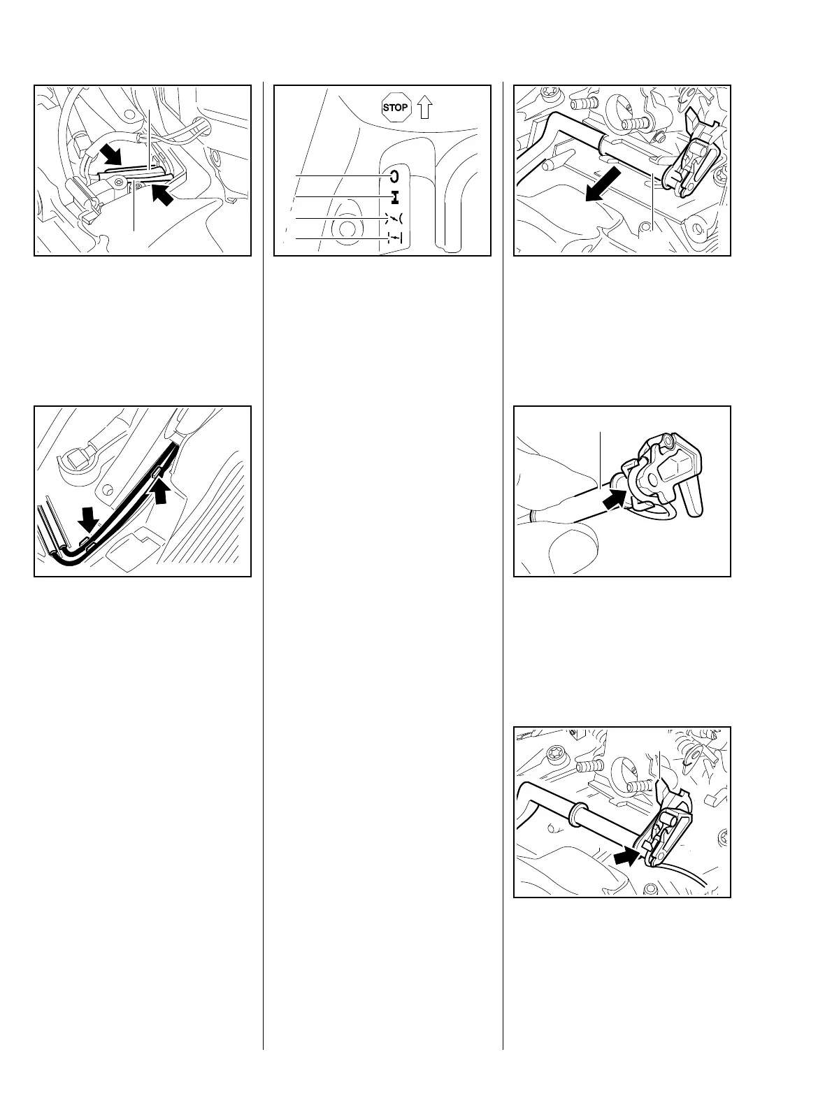
The insulating tubes must
completely enclose the plug
connections – risk of short-
circuiting.
: Press plug connections (1) into
the guides (arrows).
219RA334 TG
1
1
: Press wiring (arrows) into the
cable guides.
– Reassemble all other parts in the
reverse sequence.
– Tightening torques, b 3.5.
219RA335 TG
The following operating states are
set with the switch shaft:
– Position (1) = Engine off,
ignition is switched off
– Position (2) = Operation,
engine is running or may start
1
219RA336 TG
2
3
4
The throttle trigger interlock and
throttle trigger must be pressed
simultaneously to adjust the switch
lever from # to k or l.
– Position (3) = Hot start, engine is
already warm when it is started.
The switch shaft returns to the
operating position when the throttle
trigger is squeezed.
– Position (4) = Cold start,
engine is cold when it is started.
– Remove filter base, b 14.1.2.
: Pull out switch shaft (1).
1
219RA337 TG
– Disconnect short circuit wire from
switch shaft (arrow), b 9.6.2.
: Examine switch shaft (1) and
replace if necessary.
1
219RA338 TG
– Install short circuit wire (arrow),
b 9.6.2.
: Align switch shaft: the stop (1)
must point towards the
carburetor.
219RA339 TG
1
12. Actuating levers
12.1 Switch shaft
12.1.1 Removal and installation