27MS 441, MS 441 C
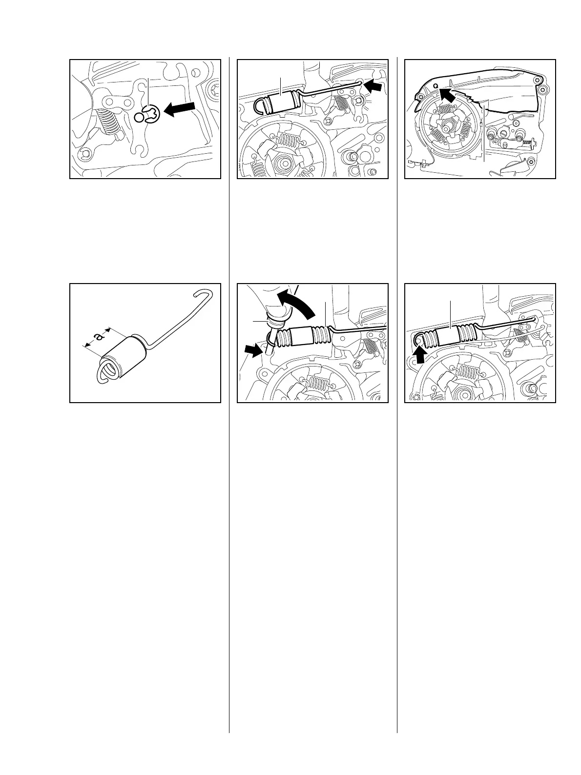
: Fit circlip (1).
219RA062 TG
1
: The turns of the brake spring
must be tightly spaced when not
installed; use a new brake spring
if necessary.
Check correct position of protective
tube: it must be centred on the
spring.
19RA063 TG
a = 20 mm
The pin for the brake spring must be
replaced if it shows signs of wear at
the groove, b 7.5.
: Hook brake spring (1) into brake
lever (arrow).
219RA064 TG
1
: Use assembly tool (2)
1117 890 0900 to attach brake
spring (1) to anchor pin (arrow).
– Reassemble all other parts in the
reverse sequence.
– Tightening torques, b 3.5.
219RA065 TG
1
2
– Grease brake lever, b 17.
The cover (1) on machines with
QuickStop Super is marked with the
letter "Q" (arrow).
219RA066 TG
1
– Troubleshooting chart, b 4.2.
– Remove shroud, b 8.4.
– Remove brake band, b 7.1.
– Push hand guard towards chain.
219RA067 TG
1
– The brake spring is now relaxed.
: Ease brake spring (1) off anchor
pin (arrow).
: Unhook brake spring (1) from
brake lever.
7.3 QuickStop Super
brake lever