26 MS 441, MS 441 C
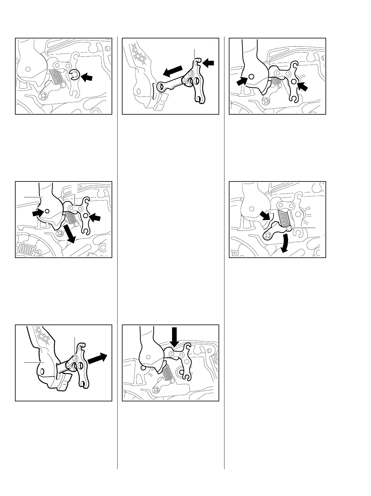
: Take out circlip (arrow).
219RA055 TG
: Draw hand guard (1) and brake
lever (2) off the pivot pins
(arrows) simultaneously.
– Take out hand guard and brake
lever.
1
2
219RA056 TG
: Pull brake lever (2) out of hand
guard (1).
– Examine brake lever and hand
guard; fit new parts if necessary.
1
2
219RA057 TG
– Examine pins and replace
if necessary, b 7.5.
– Examine cam lever and replace
if necessary, b 7.4.
Clean the dismantled parts with
a little commercially available
1
219RA058 TG
solvent-based degreasant not
containing any chlorinated or
halogenated hydrocarbons.
– Position brake lever so that
mount for brake spring (arrow) is
at the top.
: Slide brake lever (1) into recess
in hand guard until the holes are
lined up.
: Slide hand guard with brake lever
across the machine until it rests
against the pivot pin.
219RA059 TG
: Slightly lift up bearing eye of the
hand guard and brake lever and
guide the parts over the pivot pins
(arrows).
219RA060 TG
: Turn cam lever (1) aside until the
cam of the hand guard (arrow)
slides past.
– Press bearing eye of hand guard
and brake lever onto the pivot
pins.
219RA061 TG
1