33MS 441, MS 441 C
– Check correct operation and
adjust brake cable if necessary,
b 7.3.1.
: Guide fuel hose (1) under brake
cable (2) and push it onto
connector (arrow).
– Install carburetor housing,
b 14.6.2.
– Reassemble all other parts in the
219RA096 TG
1
2
reverse sequence.
– Tightening torques, b 3.5.
The cam lever defines the engaged
position of the hand guard. The
hand guard cannot be engaged in
the position "Release or apply
brake" if the spring or cam on the
cam lever or hand guard is
defective.
– Remove brake lever, b 7.2.
QuickStop Super, b 7.3.
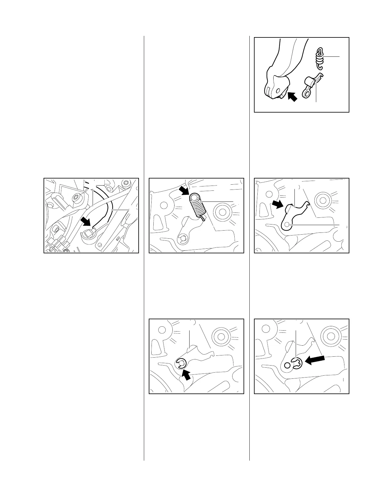
: Unhook spring (1) from anchor
pin (arrow).
219RA097 TG
1
: Take out circlip (arrow).
– Remove cam lever (1) from pivot
pin.
219RA098 TG
1
– Examine cam lever (1) and
spring (2) and fit new parts if
necessary.
– Check condition of cam guide
(arrow) and replace hand guard if
necessary.
1
219RA173 TG
2
– Position cam lever (1) so that
cam (arrow) points towards
throttle trigger.
: Slide cam lever onto pivot pin (2).
219RA099 TG
1
2
: Fit circlip (1).
219RA168 TG
1
7.4 Cam lever