124 MS 441, MS 441 C
– Drain fuel tank.
Collect fuel in a clean container and
dispose of in accordance with
environmental regulations.
– Remove front handle, b 11.5 or
b 11.5.1.
– Remove carburetor housing,
b 14.6.2.
– Remove stop buffer, b 11.4
– Remove actuating lever,
b 12.
– Remove anti-vibration springs,
b 11.
– Remove wiring harness,
b 15.8.1 in machines with
handle heating.
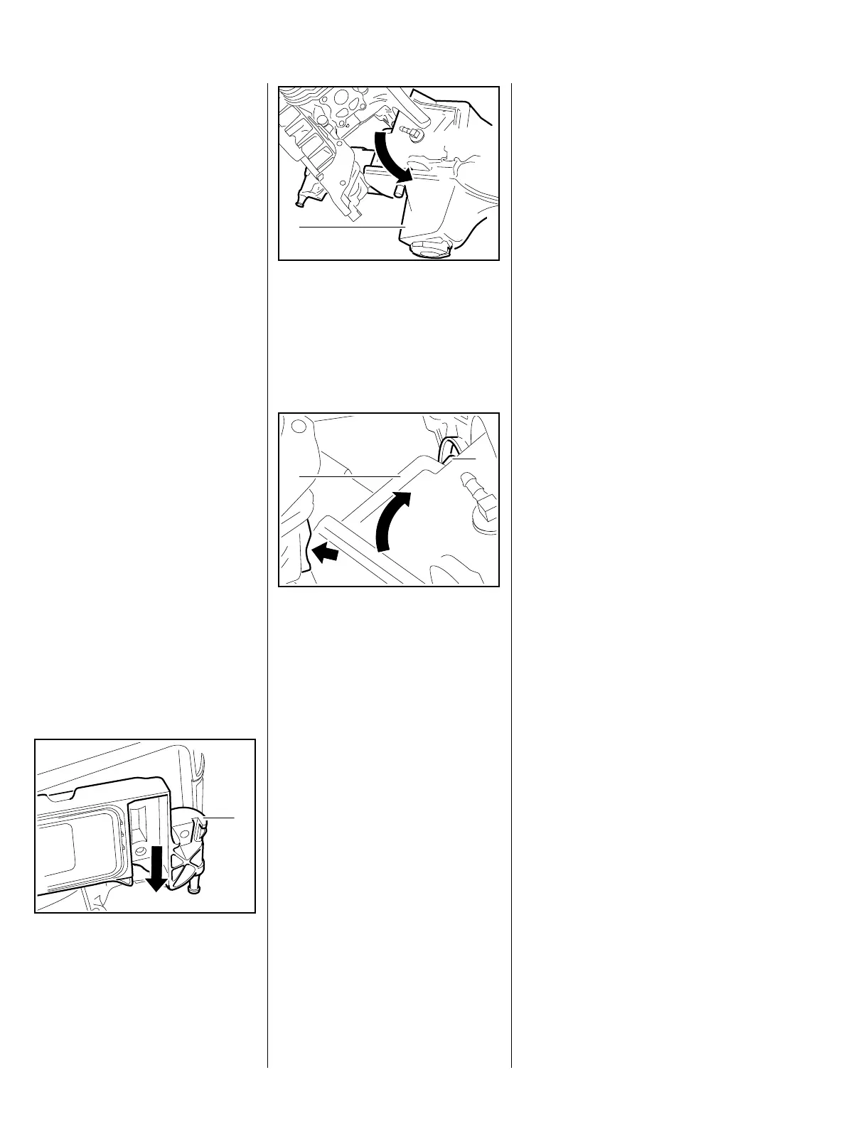
: First move front part of tank
housing (1) down and out of the
crankcase.
219RA557 TG
1
: Then turn tank housing (1) to the
side and remove it.
– Examine tank housing, replace if
necessary.
219RA558 TG
1
Only those parts of the old tank
housing should be reused which are
not included with the new tank
housing – see spare parts list.
: Fit right-hand peg (2) of tank
housing (1) into the hole of the
stop buffer on the clutch side first,
219RA554 TG
1
2
then turn it into the crankcase
past the moulded bump (arrow).
– Reassemble all other parts in the
reverse sequence.
– Tightening torques, b 3.5.
Current is supplied via wires to the
heating element installed between
filter base and carburetor.
The heating element is controlled
via the temperature regulator on the
carburetor.
The heating element must also be
checked if running problems occur
when the cold engine is idling or
running at part load, particularly at
sub-zero temperatures.
Idling problems with a hot engine
may also indicate a fault in the
heating element.
14.8.4 Tank housing, removal
and installation
15. Heating
15.1 Carburetor heating

 Loading...


