34 MS 441, MS 441 C
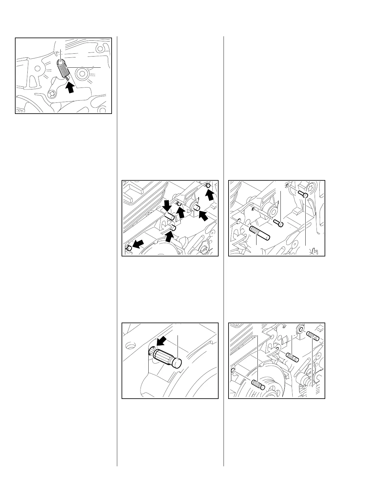
: Attach spring (1) to to cam lever
so that opening of hook (arrow)
faces towards housing.
The pin for the brake spring must be
replaced if it shows signs of wear at
the groove, b 7.5.
219RA167 TG
1
2
– Attach spring (1) to pin (2).
The cam lever is not yet tensioned,
the spring may become detached
again.
– Reassemble all other parts in the
reverse sequence.
– Tightening torques, b 3.5.
– Grease cam lever, b 17.
The pins ensure that the springs are
securely mounted. They must
therefore be replaced when worn,
otherwise the springs may pop out.
For reasons of simplicity, the parts
connected to the pins have already
been removed in the following
illustrations.
: Pull out pins (arrows) with the aid
of suitable tools.
219RA169 TG
– Wet the knurled area of the new
pin (1) with Loctite before fitting
the pin, b 17.
219RA170 TG
1
: The pin (1) must be inserted in
the hole (arrow) so that the
knurling on the pin engages the
knurled profile.
Turn the pin back and forth slightly
until it fits.
: Drive home pins (3+4+6).
3
6
4
219RA171 TG
: Drive in pins (1+2+5) as specified
below.
5
21
219RA610 TG
7.5 Pins