48 MS 441, MS 441 C
– Remove chain sprocket cover,
bar and chain, b 5.
– Remove oil pump, b 13.3.
– Remove brake band, b 7.1.
– Remove brake lever, b 7.2
QuickStop Super, b 7.3.
– Remove cylinder, b 8.5.
– Remove piston, b 8.7.
– Remove tank housing,
b 14.8.4.
– Remove flywheel, b 9.5.
– Machines with handle heating,
remove generator, b 15.7.
– Drain fuel tank and oil tank.
Fuel and oil must be disposed of in
accordance with environmental
regulations.
Always fit new ball bearings and oil
seals when the crankshaft is
removed.
Clutch side
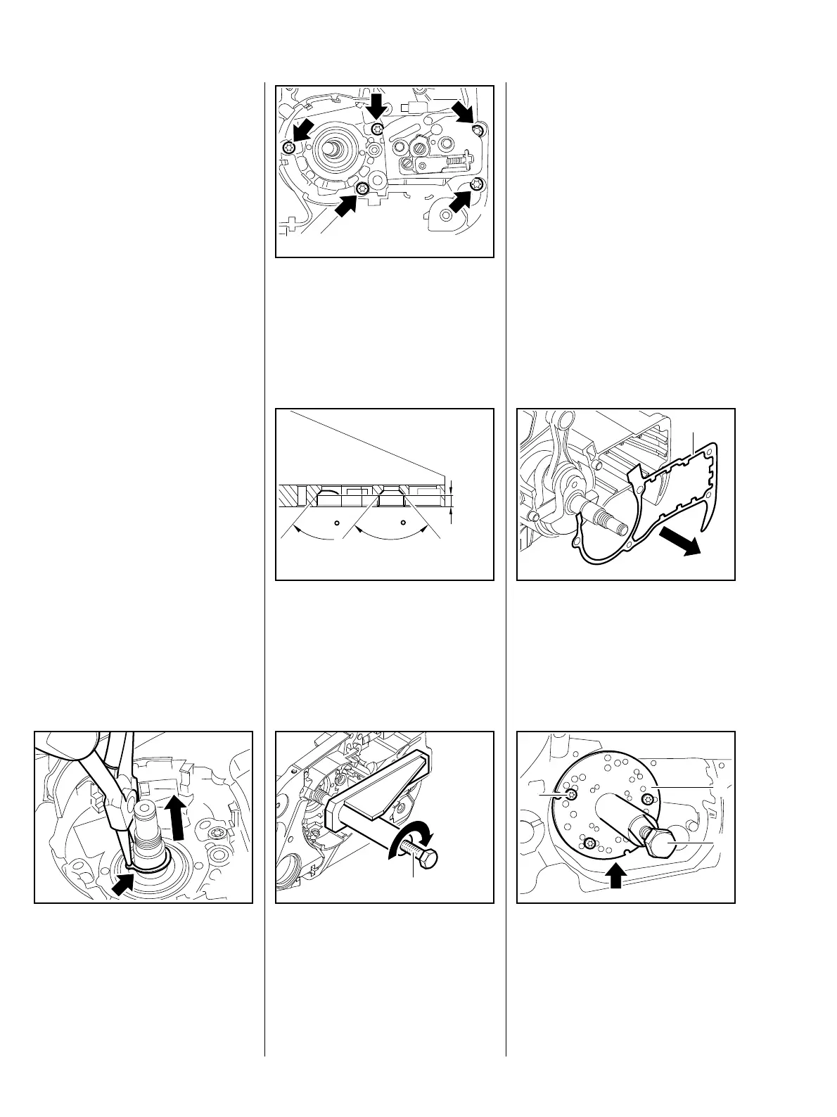
: Remove circlip (arrow).
: Take out screws (arrows).
– Remove chain tensioner, b 7.6.
219RA116 TG
: The existing removing tool
5910 890 2205 must be
reworked as illustrated.
90
90
6,5 mm
219RA117 TG
– Unscrew spindle (1) until it no
longer rests on the crankshaft
stub.
219RA118 TG
1
: Slide removing tool
5910 890 2205 over the collar
screws, screw on nuts and
tighten them down.
: Turn spindle (1) in clockwise until
the crankshaft stub has been
forced out of the ball bearing.
The crankcase half on the clutch
side is removed in this way and the
two halves of the crankcase
separated.
– Replace ball bearings and oil
seals, b 8.3 and b 8.6.3.
: Remove gasket (1).
Ignition side
219RA119 TG
1
– Unscrew spindle of assembly
tool (1) 5910 007 2220 until the
flange rests against the housing
half – left-hand thread.
20
20
20
20
219RA120 TG
2
1
3
8.6 Crankshaft
8.6.1 Removal