59MS 441, MS 441 C
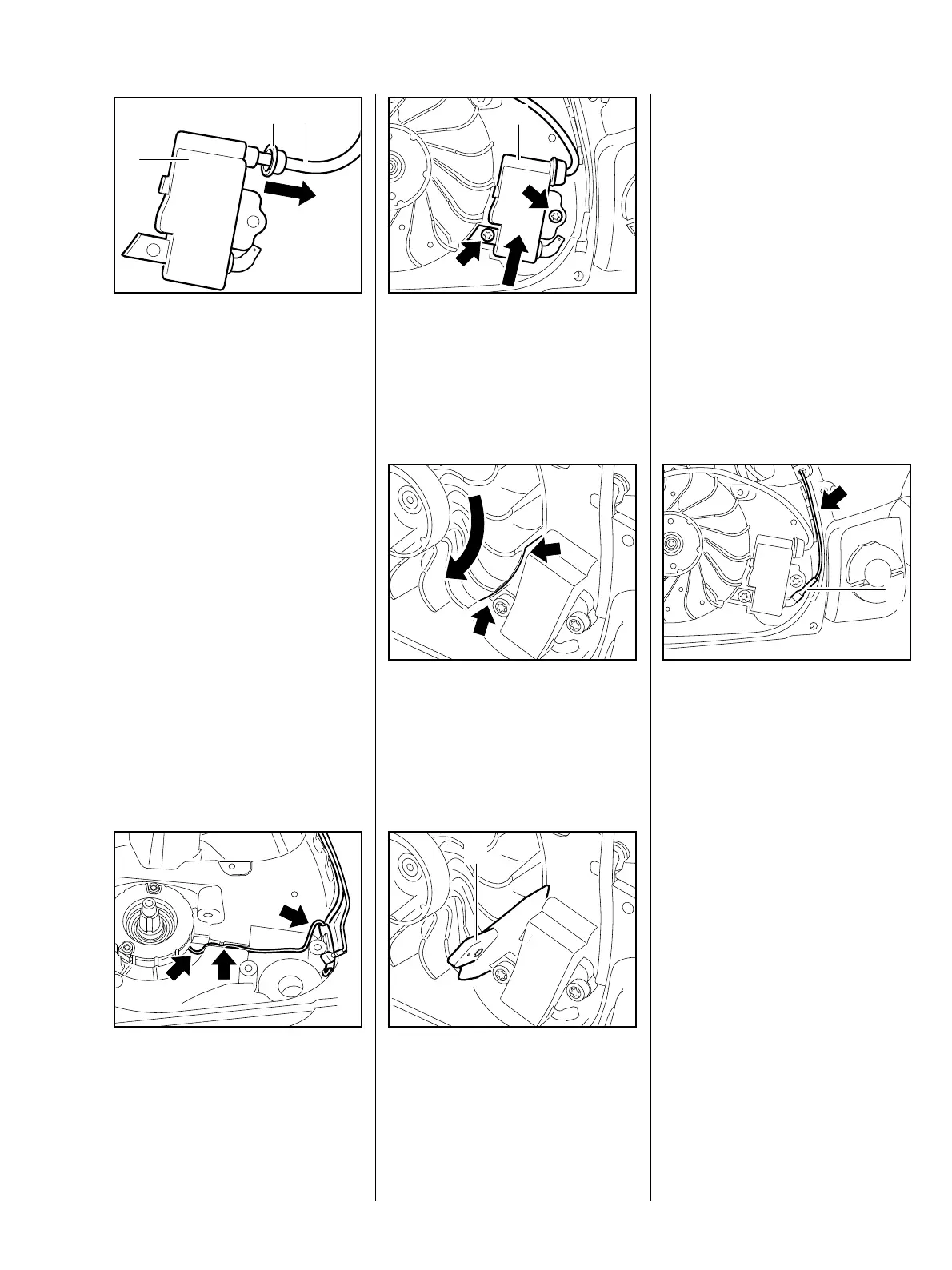
: Slide grommet (1) away from
ignition module.
: Unscrew ignition module from
ignition lead (2).
– Examine ignition module (3),
replace if necessary.
219RA372 TG
1
3
2
– Examine spark plug boot and
ignition lead, replace if
necessary, b 9.4.
– Reassemble in the reverse
sequence.
– Troubleshooting chart, b 4.5.
: Before installing the ignition
module in machines with handle
heating, ensure that the
generator lead (arrows) has been
fitted correctly, b 15.7.
219RA373 TG
: Fit ignition module (1) and insert
screws (arrows), but do not
tighten them down yet.
219RA374 TG
1
: Turn flywheel until the magnets
(arrows) are beside the ignition
module.
N
S
219RA375 TG
: Slide setting gauge (1)
1111 890 6400 between arms of
ignition module and flywheel
magnet.
N
S
219RA376 TG
1
– Press ignition module against
setting gauge.
– Tighten screws.
– Tightening torques, b 3.5.
– Pull out setting gauge.
: Connect short circuit wire (1) and
press it into the guide (arrow).
– Fit wiring harness with short
circuit wire in machines with
handle heating,
b 15.8.2 and b 9.6.2.
219RA377 TG
1