7
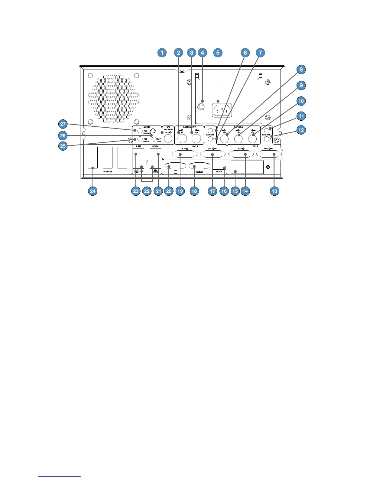
Rear Panel
1� SPI Preview – SPI Input (For future use)
2� Comp In – Composite Video Input
3� Comp Out – Composite Video Output
4� Equipotential Ground Plug – For
connection to an external protective
earthing system as described in the IEC
60601-1 Electrical Safety standard
5� AC Power Inlet
6� Primary R1 – Remote connection for
capture control on the primary channel
7� Primary R2 – Remote connection for
recording control on the primary
channel
8� S-Video IN1 – S-Video Input 1
9� S-Video IN2 – S-Video Input 2
10� S-Video Out – S-Video Output
11� Secondary R1 – Remote connection for
capture control for secondary channel
12� Secondary R2 – Remote connection for
recording control for secondary channel
13� DVI 2 Out – Secondary Channel DVI
Output
14� DVI 2 In – Secondary Channel DVI Input
15� SFB Connector Ports – Enables Firewire
connection with Stryker Firewire devices
16� eSATA – Compatible eSATA Cable Port (For
future use)
17� DVI 1 Out – Primary Channel Output
18� Serial Port
19� DVI 1 In – Primary Channel Input
20� VGA
21� SORN – RJ45 SORN Port
22� USB Ports for mouse, keyboard, printer
23� RJ45 Port – Network Port
24� Devices – Stryker Devices Port
25� Line-In – Audio Input
26� Line-Out – Audio Output
27� Headset – Audio In/Headset Out