5-18 Sun Fire X4150 Server Service Manual • November 2009
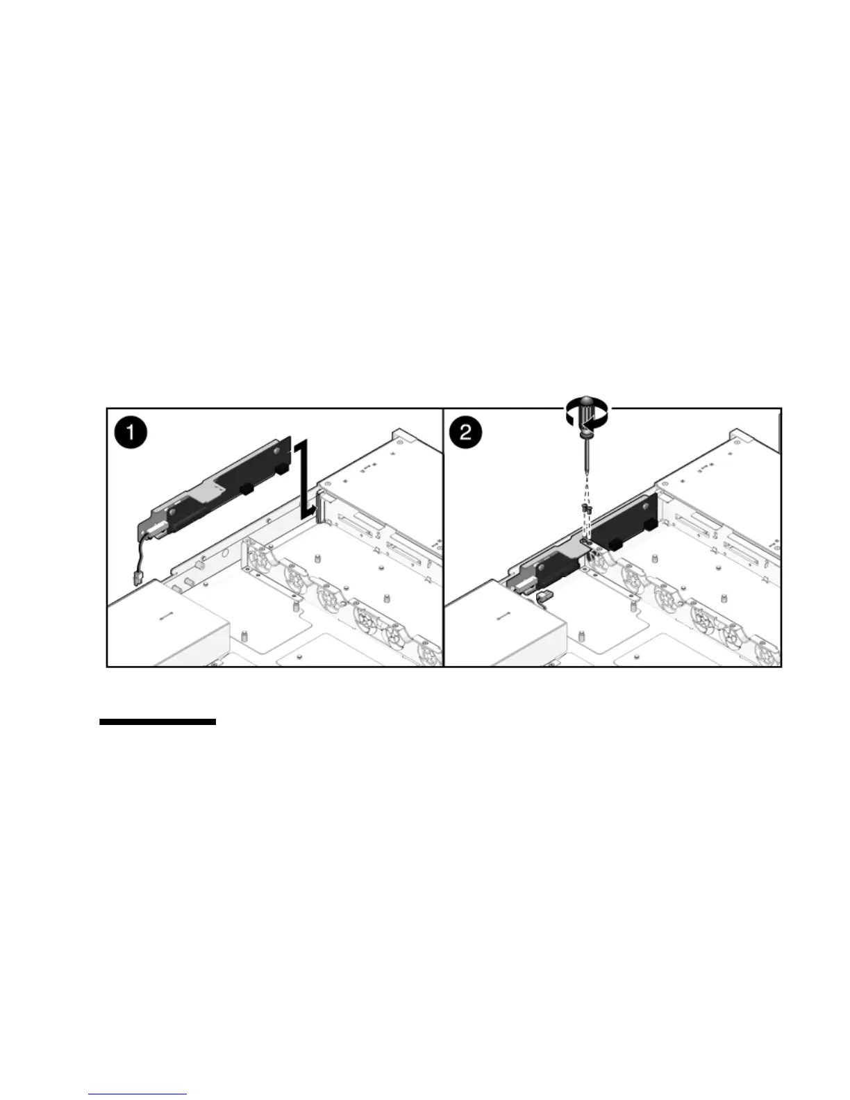
2. Slide the paddle card forward to plug it into the drives backplane (FIGURE 5-11).
3. Secure the paddle card with two No. 2 Phillips screws.
4. Install the fan power boards.
See Section 5.1.2, “Installing a Fan Power Board” on page 5-3.
5. Install the power distribution board.
See Section 5.5.2, “Installing the Power Distribution Board” on page 5-15.
6. Install the motherboard assembly.
See Section 4.6.1, “To Install the Motherboard Assembly” on page 4-25.
FIGURE 5-11 Installing the Paddle Card
5.7 Servicing Cables
The following topics are covered:
■ Section 5.7.1, “Removing Drive Cables in a SAS Configuration” on page 5-19
■ Section 5.7.2, “Installing Drives Cables in a SAS Configuration” on page 5-20
■ Section 5.7.3, “Removing Drive Cables in a SATA Configuration” on page 5-22
■ Section 5.7.4, “Installing Drive Cables in a SATA Configuration” on page 5-24
■ Section 5.7.5, “Changing Drive Cables from SAS to SATA” on page 5-26
■ Section 5.7.6, “Change Drive Cables from SATA to SAS” on page 5-27