Lighting Systems: 9B-11
Hazard Switch Inspection
B649G19206028
Inspect the hazard switch in the following procedures:
1) Remove the right frame head cover. (GSF1200)
Refer to “Exterior Parts Removal and Installation: in
Section 9D”.
2) Disconnect the left handlebar switch coupler (1).
3) Inspect the hazard switch for continuity with a tester.
If any abnormality is found, replace the left
handlebar switch assembly with a new one. Refer to
“Handlebars Removal and Installation: in Section
6B”.
Special tool
: 09900–25008 (Multi-circuit tester set)
Tester knob indication
Continuity ( )
4) After finishing the hazard switch inspection, reinstall
the removed parts.
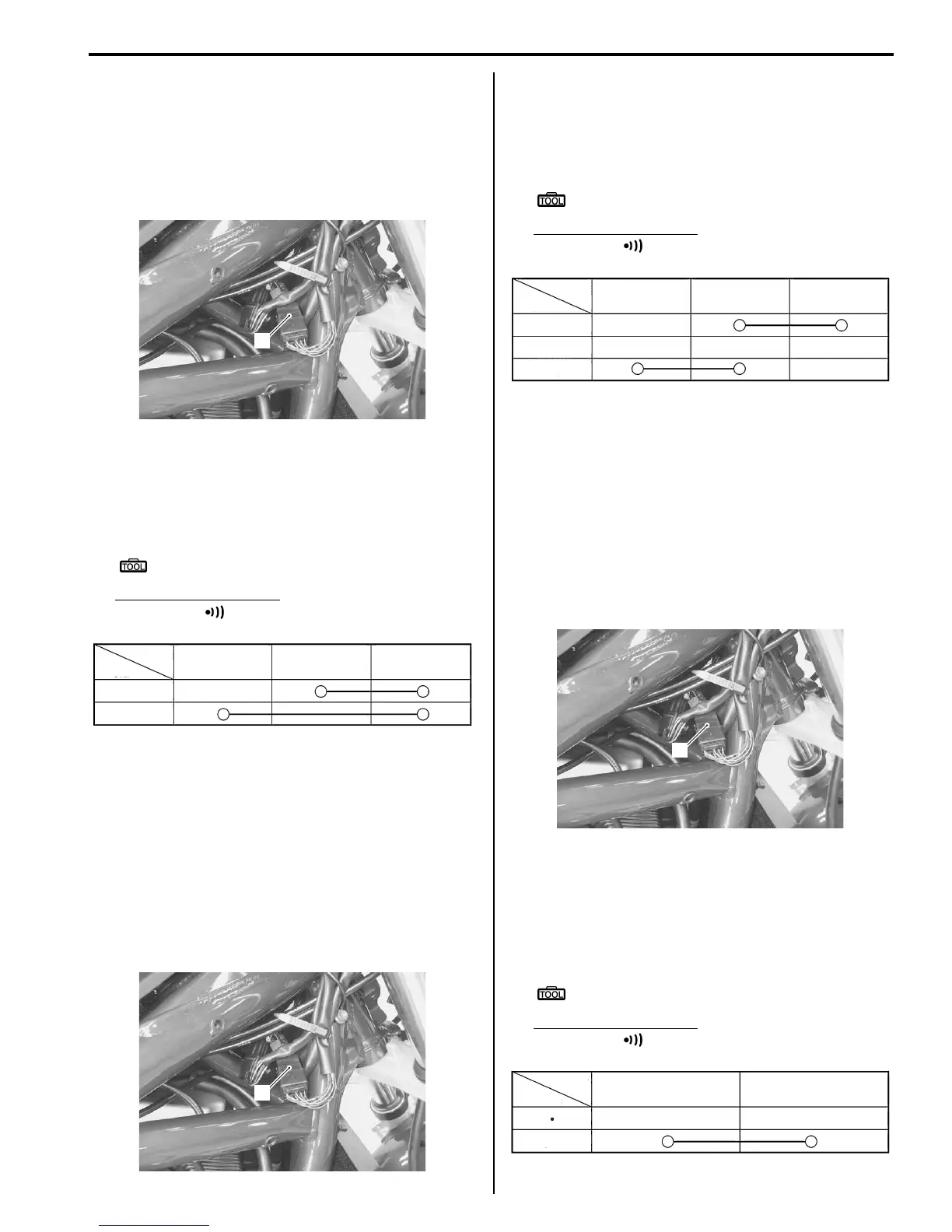
Turn Signal Switch Inspection
B649G19206029
Inspect the turn signal switch in the following
procedures:
1) Remove the right frame head cover. (GSF1200)
Refer to “Exterior Parts Removal and Installation: in
Section 9D”.
2) Disconnect the left handlebar switch coupler (1).
3) Inspect the turn signal switch for continuity with a
tester. If any abnormality is found, replace the left
handlebar switch assembly with a new one.
Refer to “Handlebars Removal and Installation: in
Section 6B”.
Special tool
: 09900–25008 (Multi-circuit tester set)
Tester knob indication
Continuity ( )
4) After finishing the turn signal switch inspection,
reinstall the removed parts.
Passing Light Switch Inspection
B649G19206030
Inspect the passing light switch in the following
procedures:
1) Remove the right frame head cover. (GSF1200)
Refer to “Exterior Parts Removal and Installation: in
Section 9D”.
2) Disconnect the left handlebar switch coupler (1).
3) Inspect the passing light switch for continuity with a
tester.
If any abnormality is found, replace the left
handlebar switch assembly with a new one.
Refer to “Handlebars Removal and Installation: in
Section 6B”.
Special tool
: 09900–25008 (Multi-circuit tester set)
Tester knob indication
Continuity ( )
1
I649G1920036-01
Position
Color
OFF
ON
B B/Br B/G
I649G1920040-01
1
I649G1920036-01
L
PUSH
R
B/G B/Br B
Color
Position
I649G1920037-01
1
I649G1920036-01
PUSH
Position
Color
G/B Dg
I649G1920038-01

 Loading...


