1B-4 Emission Control Devices:
Schematic and Routing Diagram
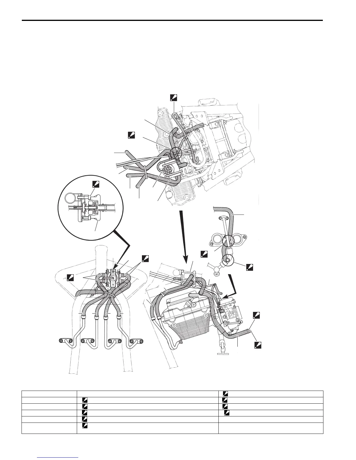
PAIR System Hose Routing Diagram
B649G11202001
5
2
3
4
1
6
7
7
7
1234
1
2
7
6
5
5
“D”
“A”
“I”
“C”
“B”
“H”
“E”
“G”
“F”
I649G1120008-04
1. PAIR hose No.1 7. PAIR control valve “F”: Marking (White) must face front side.
2. PAIR hose No.2 “A”: Be careful not to contact the PAIR hoses with the throttle cables. “G”: Marking (White) must face rear side.
3. PAIR hose No.3 “B”: Pass the PAIR hose (5) in front of the oil pipe. “H”: Marking (White) must face top side.
4. PAIR hose No.4 “C”: Pass the PAIR hose (5) through inside of the oil pipe. “I”: Connect the vacuum hose to No.4 carburetor.
5. PAIR hose (Fresh air) “D”: Install the PAIR control valve along with its bracket.
6. Vacuum hose “E”: Connect the PAIR hose (5) to the air cleaner box. (Fresh air from
air cleaner box.)

 Loading...


