Engine Mechanical: 1D-25
Cooling Hose
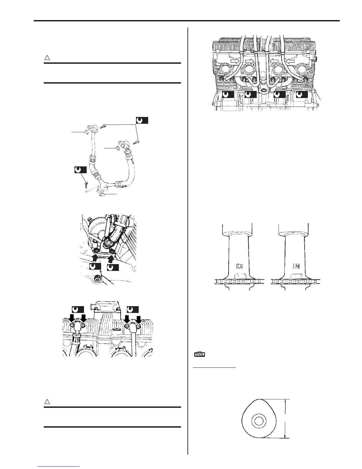
• Install the left and right cooling hoses and tighten their
mounting bolts to the specified torque.
CAUTION
!
Replace the O-rings (1) with new ones to
prevent oil leakage.
Tightening torque
Cooling hose mounting bolt (a): 10 N·m (1.0 kgf-
m, 7.0 lb-ft)
PAIR Pipe / Hose
• Install the PAIR pipes and hoses and tighten their
mounting nuts to the specified torque.
CAUTION
!
Replace the gaskets with new ones to
prevent exhaust gas leakage.
Tightening torque
PAIR pipe mounting nut (a): 10 N·m (1.0 kgf-m,
7.0 lb-ft)
Valve Clearance Inspection and Adjustment
B649G11406067
Refer to “Valve Clearance Inspection and Adjustment: in
Section 0B”.
Camshaft Inspection
B649G11406048
Refer to “Engine Top Side Disassembly: ”.
Refer to “Engine Top Side Assembly: ”.
Camshaft Identification
The exhaust camshaft has the embossed letters “EX”
and the intake camshaft has the embossed letters “IN”.
Cam Wear
Check the camshaft for wear or damage.
Measure the cam height “a” with a micrometer.
Replace a camshaft if the cams are worn to the service
limit.
Special tool
: 09900–20202 (Micrometer (25-50mm))
Cam height “a”
Service limit: (IN) 33.28 mm (1.3102 in)
Service limit: (EX) 32.35 mm (1.2736 in)
1
1
1
(a)
(a)
I649G1140089-02
(a)
(a)
I649G1140090-02
(a) (a)
I649G1140091-02
(a) (a) (a) (a)
I649G1140093-02
I649G1140198-01
“a”
I649G1140199-01

 Loading...


