COOLING AND LUBRICATION SYSTEM 7-15
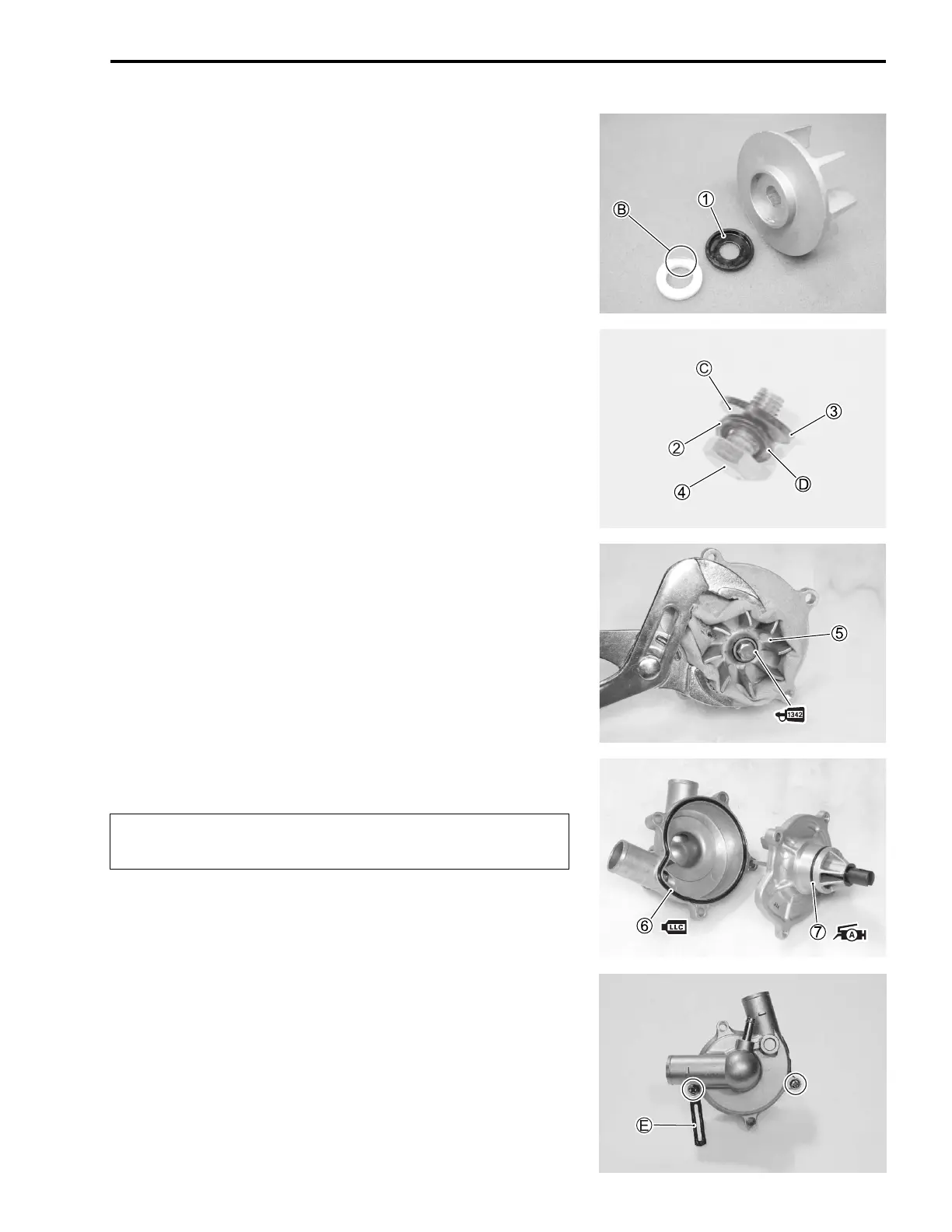
• Install the rubber seal 1 into the impeller.
• After wiping off the oily or greasy matter from the mechanical
seal ring, install it into the impeller.
NOTE:
The paint marked side B of mechanical seal ring faces the rub-
ber seal.
• Install the washer 2 and seal washer 3 onto the impeller
securing bolt 4.
NOTE:
The metal side C of seal washer and the curved side D of
washer face the impeller securing bolt head.
• Install the impeller 5 and its securing bolt onto the shaft.
• Tighten the impeller securing bolt to the specified torque.
Impeller securing bolt: 8 N·m (0.8 kgf-m, 6.0 lb-ft)
NOTE:
Before installing the impeller securing bolt, apply a small quan-
tity of the THREAD LOCK to it.
99000-32050: THREAD LOCK “1342”
• Install the new O-rings 6 and 7.
NOTE:
* Apply engine coolant to the O-ring 6.
* Apply SUZUKI SUPER GREASE “A” to the O-ring 7.
99000-25030: SUZUKI SUPER GREASE “A” (USA)
99000-25010: SUZUKI SUPER GREASE “A” (Others)
• Tighten the water pump cover screws to the specified torque.
Water pump cover screw: 5 N·m (0.5 kgf-m, 3.5 lb-ft)
NOTE:
Fit the clamp E to the water pump cover screw.
Use the new O-rings to prevent engine coolant leak-
age.
SAMPLE

 Loading...


