DRIVE TRAIN 4-39
RIGHT SIDE SHIM SELECTION
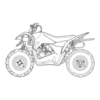
• After the backlash has been checked or adjusted, put a few
pieces of solder (O.D.: 1.2 – 1.5 mm × L: 6 mm) on the ring
gear back side, as shown.
NOTE:
* Do not install the right side shim(s) at this time.
* Apply a small quantity of grease to the solders to prevent them
from falling.
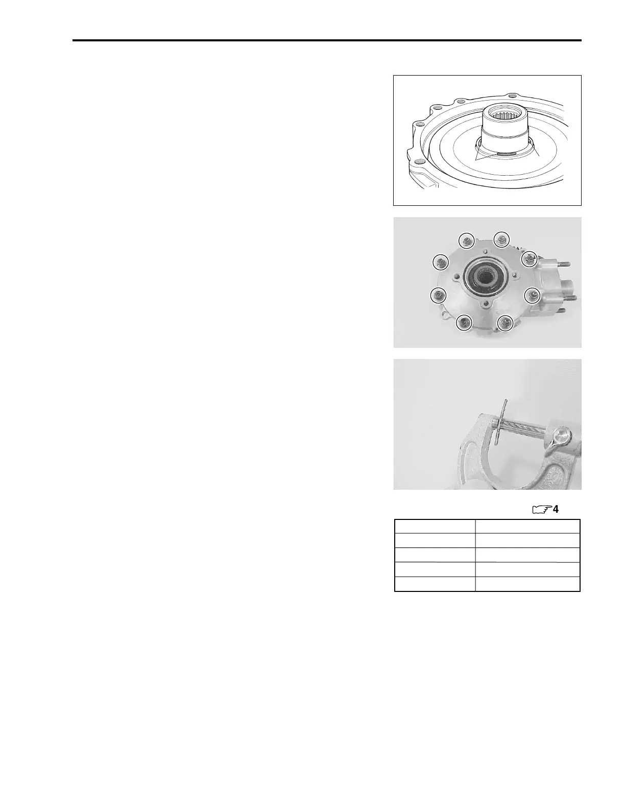
• Install the gear case cover and tighten its bolts to the speci-
fied torque in a crisscross pattern. (!4-33)
NOTE:
* Do not install the new O-ring to the gear case cover.
* Do not apply a thread lock to the case cover bolts.
( Gear case cover bolt: 23 N·m (2.3 kgf-m, 16.5 lb-ft)
• Remove the gear case cover. (!4-26)
• Measure the thickness of compressed solder with the
micrometer.
# 09900-20205: Micrometer
• Select the proper size of shim(s) from the right chart, accord-
ing as the compressed solder thickness.
• After selecting the proper size of shim(s), install it on the ring
gear back side.
Solder
Solder
Part No.
Shim thickness
For right side of ring gear (
:
4-40)
27326-18A00-035 0.35 mm (0.0138 in)
27326-18A00-040 0.40 mm (0.0157 in)
27326-18A00-050 0.50 mm (0.0197 in)
27326-18A00-060 0.60 mm (0.0236 in)

 Loading...