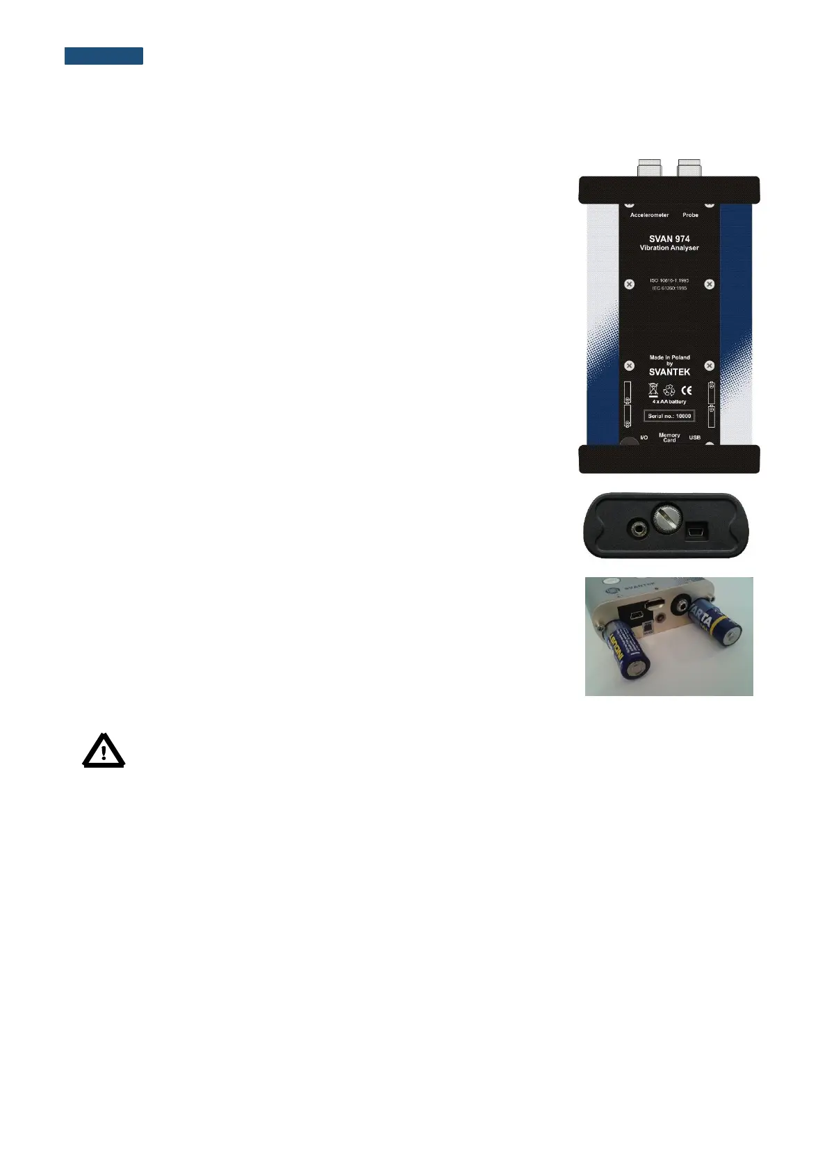
Top cover of the instrument
The instrument inputs, called Accelerometer and Probe are placed in the
centre of the instrument’s top cover. The Accelerometer Input may work in three
modes (Acceler. IEPE, Acceler. Charge and Acceler. Voltage) and the user
should connect proper accelerometer to this input or voltage using TNC
connector. The Probe input is dedicated for connection with the tachometer.
The accelerometers should be connected to the instrument using the TNC
connector. After connecting the preamplifier or the accelerometer cable to the
measurement input, the screw should be tightened to light resistance only. Do
not over tighten this connector. The full description of the signals connected to
the sockets is given in Appendix C.
Bottom cover of the instrument
In the bottom cover, there are two sockets, placed from the right to the left as
follows: I/O and USB.
The USB socket is the USB Device 1.1 interface – a serial interface working with
12 MHz clock. Thanks to its speed, it is widely used in all PCs. In the instrument,
the standard 4-pin socket is used.
The additional multi-purpose input / output socket, called I/O, is a 3.5 mm jack
socket. On this socket, in case when the Analogue Output functionality is
selected, the signal from the input of the analogue / digital converter (before any
frequency correction) is available. This signal can be recorded using a magnetic
recorder or observed on an oscilloscope. The Digital Input as another
functionality that serves as the external trigger to the instrument, while the Digital
Output is used to generate the trigger pulse or alarm pulse from the instrument.
There is a memory micro SD-card slot under the bottom cover of the instrument
and spaces for the 4 x AA batteries.
All sockets are described in detail in the Attachment C for this manual.