5.4.3 Selection of additional summary results for saving – Summary Results
The Summary Results list enables the user
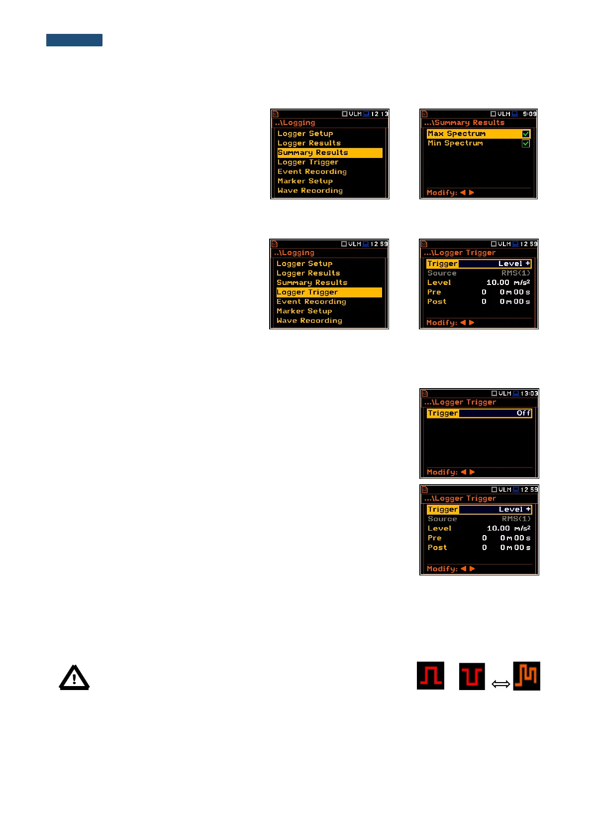
to activate additional to the main results
saving in the logger file: Max Spectrum and
Min Spectrum.
5.4.4 Setting up the logger trigger parameters – Logger Trigger
The Logger Trigger parameters influence
the way the measurement results are saved
in the logger. It is a context sub-list in which:
the trigger can be switched off or it’s type
selected (Trigger), the source of the
triggering signal can be determined (Source),
it’s level can be selected (Level), as well as
the number of the results saved in the logger
before the fulfilment of the triggering condition
(Pre) and the number of the results saved in
the logger after the fulfilment of the triggering
condition (Post) defined.
Trigger disabling
The logger triggering of the measurements (Trigger) can be switched off using
the ◄ or ► push-button. The triggering is switched on if the Level + or Level –
mode is selected.
Level type trigger
If the triggering signal is greater than the selected in Level + or less than Level -
, the logger contains:
• the measurement results recorded directly before the fulfilment of the
triggering condition; time of the recording can be calculated by multiplying the
value set in the Pre position by the time period taken from the Logger Step
(path: <Menu> / Measurement / Logging / Logger Setup);
• all measurement results up to the moment the triggering signal falls below
the Level;
• the results recorded directly after the fulfilment of the triggering condition;
time of the recording can be calculated by multiplying the value set in the
Post by the period taken from the Logger Step (path: <Menu> /
Measurement / Logging / Logger Setup).
Note: When logger is waiting for the level trigger the “trigger level”
icon appears alternatively with the „curve” icon.
Source of the triggering signal
When the Level Meter mode is chosen only one measured result can be used as a source of the triggering signal
in the logger, namely the output signal from the RMS detector coming from the first profile which is denoted here
as RMS(1). This position does not become active (it is shown greyed out) and the text stated here remains
unchanged.