The I/O jack socket can be used as:
• the output of the analogue signal (Analog Out) transmitted from the input
of the instrument to its output without any digital processing (i.e. frequency
filtering),
• the input of the digital signal used as an external trigger to start the
measurements (Digital In). The instrument is acting in this case as so
called “slave instrument”,
• the digital output (Digital Out) used for triggering other “slave
instrument(s)” (the instrument is acting in this case as a “master
instrument”), or as a source of any alarm signal in case of certain
circumstances occurred during the measurements (i.e. the level of the input
signal was higher than a user selected trigger alarm setting).
The more detailed description of the I/O socket is given in App. C.
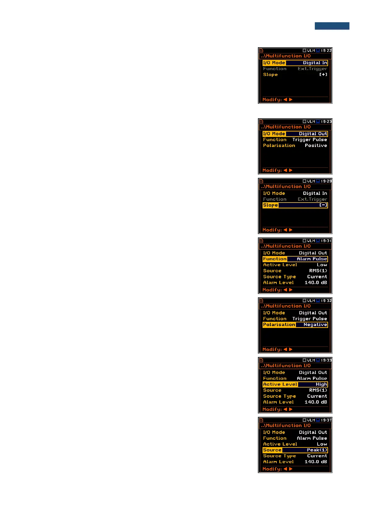
Slope parameter for the Digital In mode (Ext.Trigger function)
In case of Digital In the signal appeared on the I/O socket will be be treated
as the external trigger if External is chosen as a trigger (path: <Menu> /
Measurement / Measurement Trigger / Trigger: External). For the Digital In
mode only the Ext.Trigger value is available for the parameter Function. It is
possible to set up Slope as positive [+] or negative [-] by means of the ◄ or
► push-buttons.
Digital output function of the I/O socket
The Function position enables the user to set the function of the digital output
of the I/O instrument’s socket. The socket can be used as the source of the
trigger pulse (Trigger Pulse) which starts the measurement in another “slave
instrument” linked to the “master instrument” or the alarm signal, which
appears there after fulfilling certain measurement conditions (Alarm Pulse).
Polarisation of the digital output signal
The Polarisation position enables the user to select which polarisation of the
signal (negative or positive) will be applied to the output trigger pulse.
Active level for the alarm pulse generation
The Active Level position enables the user to select which level of the signal
should be treated as a valid one (“negative” or “positive” logic): Low or High.
Source signal for the alarm pulse generation
The Source position enables the user to select the level of which
measurement result should be checked. If the measured result level is greater
than selected alarm level (Alarm Level), the instrument will generate alarm
signal on the I/O socket. The measurement results from the first profile:
Peak(1), Spl(1), Max(1) or Leq(1) can be used for the purpose described
above.