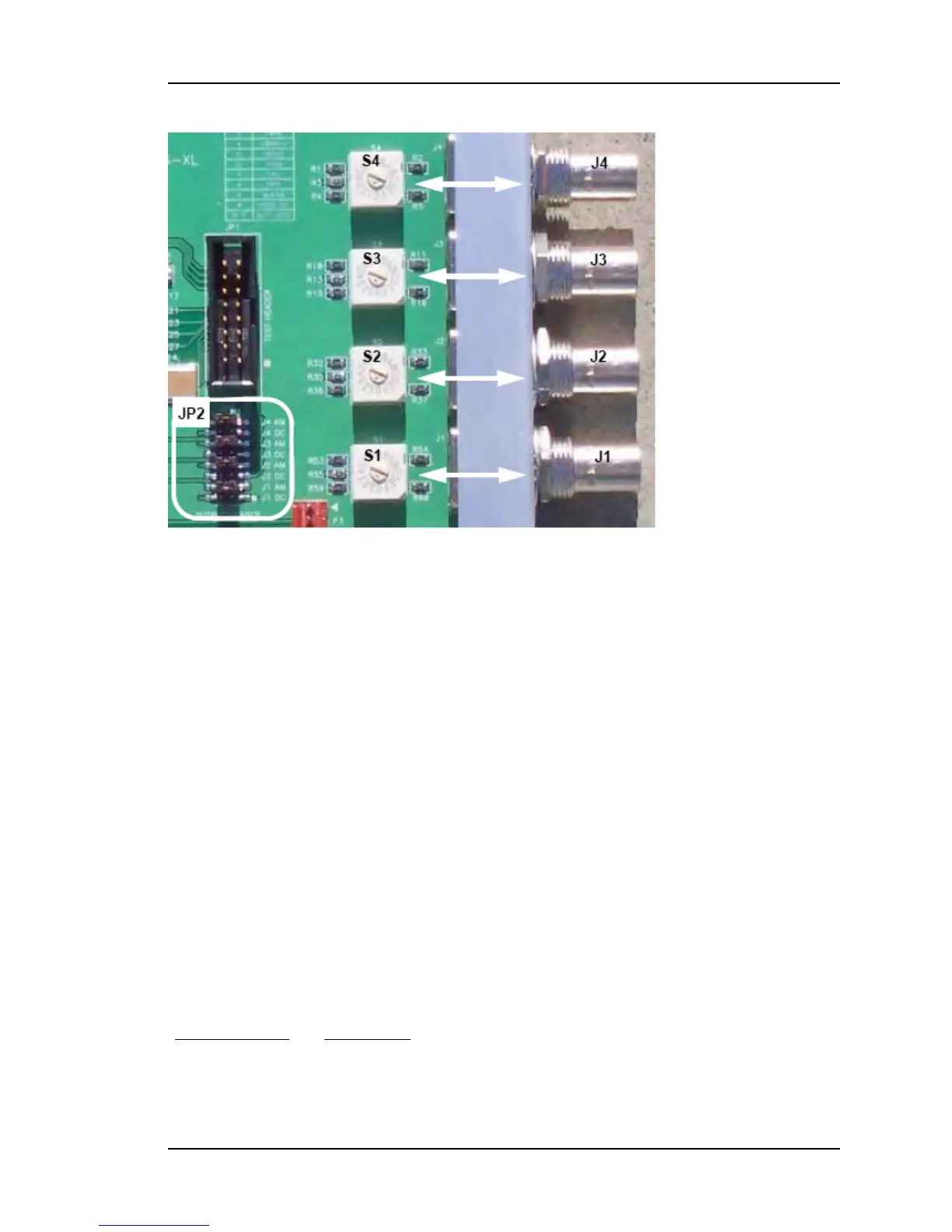
Configuring the Expansion Module
To change the configuration, identify the jumper at JP2 (shown above) that corresponds to
the output you are configuring. JP2 has four pairs of jumper selectable settings, one pair for
each output signal BNCconnector, J1, J2, J3, and J4. Each of the four JP2 pairs has a AM
and a DC position. Also associated with each output signal connector is a rotary signal
selector switch, S1, S2, S3, and S4.
To generate AM time code, if necessary, move the jumper in JP2 to the AM jumper. For
example, to generate IRIG-B AM on the J4 output BNCconector, move the jumper from J4
DC to J4 AM jumper position. At this point the configuration procedure would be complete.
To generate any other signal type, three steps are required.
1. Move the plug in JP2 to the DC jumper (e.g., J4 DC).
2. Select a signal type from the following table and note the corresponding switch posi-
tion (e.g., 10 MPPS = position 1).
3. Using a small flat-head screwdriver, turn the rotary switch (e.g., S4) to the appro-
priate switch position (e.g., 1). In this example, the J4 output would be set to gen-
erate 10 MPPS and the procedure would be complete. The same method can be used
to configure any of the outputs.
Switch Position Signal Type
0 Off
098-00116-000 Rev. A............................... Page 155 of 221
 Loading...