Appendix
B:
Specification
4
J
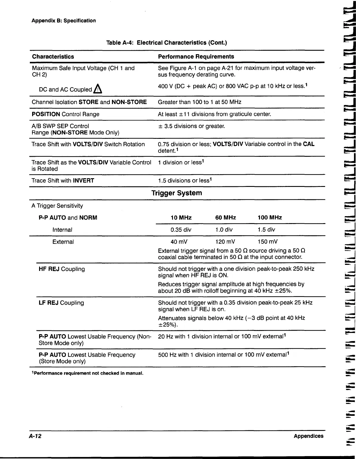
Table A-4: Electrical Characteristics (Cont.)
Characteristics Performance Requirements
Maximum Safe Input Voltage (CH 1 and
See Figure
A-1
on page A-21 for maximum input voltage ver-
CH 2)
sus frequency derating curve.
DC and AC coupled
A
400 V (DC
+
peak AC) or 800 VAC p-p at 10 kHz or less.'
Channel Isolation
STORE
and
NON-STORE
Greater than 100 to
1
at 50 MHz
POSITION
Control Range
At least
+
1 1 divisions from graticule center.
AIB SWP SEP Control
+
3.5 divisions or greater.
Range
(NON-STORE
Mode Only)
Trace Shift with
VOLTSIDIV
Switch Rotation
0.75 division or less;
VOLTSIDIV
Variable control in the
CAL
detent.'
Trace Shift as the
VOLTSIDIV
Variable Control 1 division or less1
-I
is Rotated
Trace Shift with
INVERT
1.5 divisions or less1
51
e"l
Trigger System
A Trigger Sensitivity
P-P AUTO
and
NORM
Internal
10
MHz
60
MHz
100
MHz
0.35 div
1.0 div
1.5
div
External
External trigger signal from a 50
f2
source driving a 50
f2
coaxial cable terminated in 50
f2
at the input connector.
HF
REJ
Coupling
Should not trigger with a one division peak-to-peak 250 kHz
signal when
HF
REJ is ON.
Reduces trigger signal amplitude at high frequencies by
about 20 dB with
rolloff beginning at 40 kHz 225%.
LF REJ
Coupling
Should not trigger with a 0.35 division peak-to-peak 25 kHz
I
signal when LF REJ is on.
1
-
Attenuates signals below 40 kHz (-3 dB point at 40 kHz
L
P-P AUTO
Lowest Usable Frequency (Non-
20 Hz with 1 division internal or 100
mV external1
Store Mode only)
4
!!!+
P-P AUTO
Lowest Usable Frequency
500 Hz with
1
division internal or 100 mV external1
a
(Store Mode only)
E?
'Performance requirement not checked in manual.
^II
P
A-72
Appendices
-
-
L
 Loading...


