Appendix
B:
Specification
[
Table
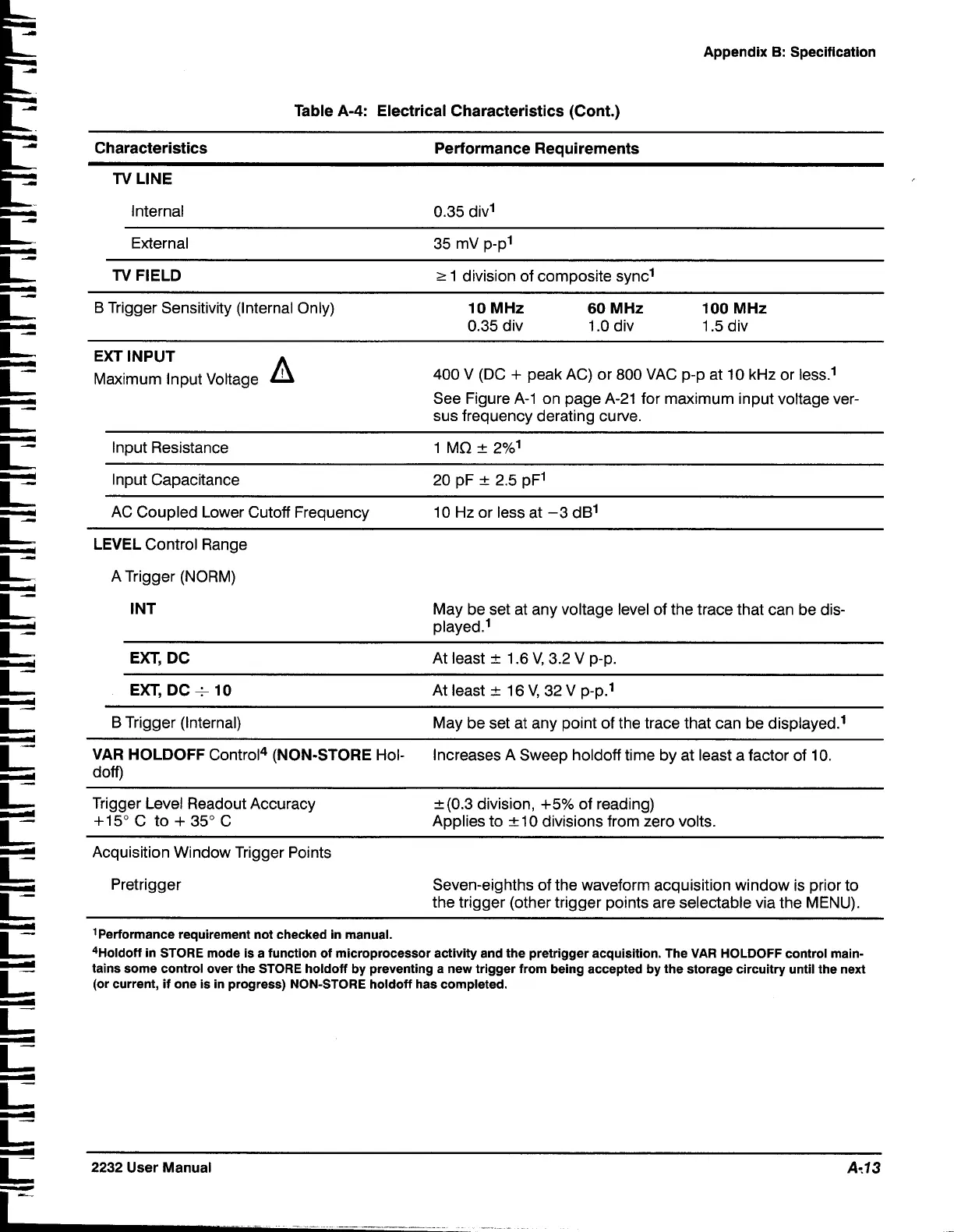
A-4:
Electrical Characteristics (Cont.)
Characteristics Performance Requirements
TV
LINE
L-
Internal 0.35 divl
External
35
mV p-p1
Ls
TV
FIELD
r
1 division of composite sync1
C
B
Trigger Sensitivity (Internal Only)
10 MHz
60 MHz 100 MHz
0.35 div 1.0 div 1.5 div
C
EXTINPUT
r
Maximum Input Voltage
A
400 V (DC
+
peak AC) or 800 VAC p-p at 10 kHz or less.'
I-
See Figure A-1 on page A-21 for maximum input voltage ver-
sus frequency derating curve.
I
I-
Input Resistance 1 MQ
+
2%'
p
Input Capacitance 20 pF
+
2.5 pFI
I
I-..;
AC Coupled Lower Cutoff Frequency 1
0
Hz or less at -3 dB1
LEVEL
Control Range
A Trigger (NORM)
I NT
May be set at any voltage level of the trace that can be dis-
played.'
EXT, DC
At least
+
1.6 V, 3.2 V p-p.
E?
EXT, DC+ 10
At least
+
16 V, 32 V p-p.'
B Trigger (Internal)
May be set at any point of the trace that can be displayed.'
-
-
VAR HOLDOFF
Control4
(NON-STORE
Hol-
Increases A Sweep
holdoff time by at least a factor of 10.
doff)
I-
Trigger Level Readout Accuracy
+15" C to
+
35" C
k(0.3 division, +5% of reading)
Applies to
+
10 divisions from zero volts.
Acquisition Window Trigger Points
Pretrigger
Seven-eighths of the waveform acquisition window is prior to
the trigger (other trigger points are selectable via the MENU).
'Performance requirement not checked in manual.
4Holdoff in STORE mode is a function of microprocessor activity and the pretrigger acquisition. The VAR HOLDOFF control main-
tains some control over the STORE
holdoff
by
preventing a new trigger from being accepted by the storage circuitry until the next
(or current, if one is in progress) NON-STORE
holdoff has completed.
2232
User Manual
At13
 Loading...


