8: Testing flash memory Model 4200A-SCS Pulse Card (PGU and PMU)
8-4 4200A-PMU-900-01 Rev. B March 2023
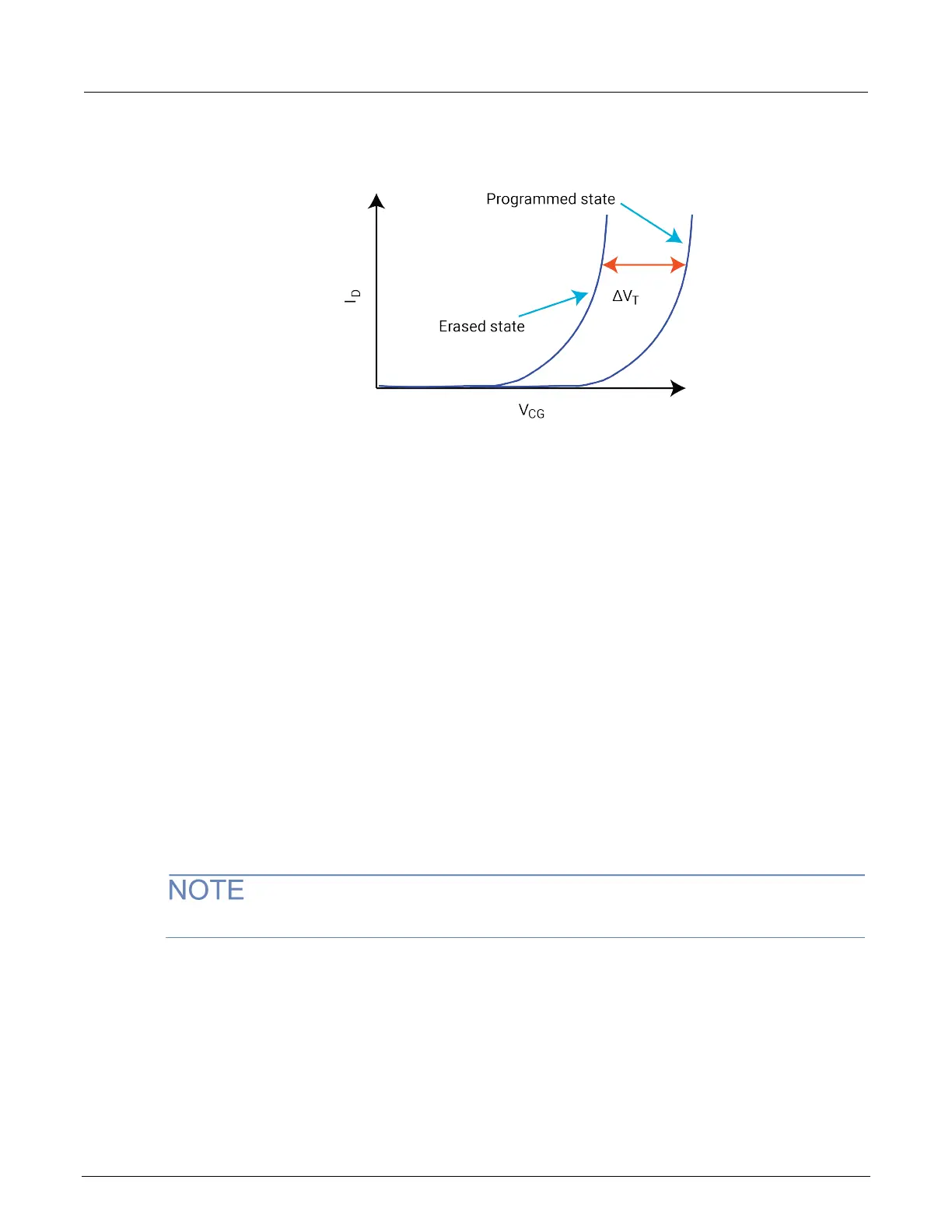
Figure 154: Graph of shifted voltage threshold, VT, due to stored charge on floating gate on a
1 bit (2 level) cell
The Flash transistors tests consist of two parts:
1. Pulse waveforms that program or erase the DUT
2. DC measurements are made to determine the state of the device
This implies switching between two conditions:
1. Pulse resources are connected to the DUT
2. Pulse resources are disconnected and the DC resources are connected to the DUT
The pulses are used to move charge to or from the floating gate. There are two different
methods to move charge:
1. Tunneling
2. Hot charge injection (HCI)
The tunneling method is commonly known as Fowler-Nordheim (FN) tunneling, or quantum tunneling,
and is a function of the electric potential across the tunneling oxide. HCI is considered a damage
mechanism in nonfloating gate transistors. HCI is a method that accelerates charges by applying a
drain-source field, and then the charges are directed into the floating gate by a gate voltage.
The drain and source are not connected to any test instrumentation.
There are many other ways to provide similar electric fields and balance performance across a variety
of parameters: program or erase speed, retention longevity, adjacent cell disturbance, endurance,
and others.
The following figure shows examples of tunneling to move charge to and from the FG.
• The electric field and the preferred direction of electron flow are indicated by the black arrows.
• The signal applied to each device terminal is indicated by the blue text and blue features.
 Loading...