-SCS Pulse Card (PGU and PMU) User's Manual Section 3:
Setting up PMUs and PGUs in Clarius
4200A-PMU-900-01 Rev. B March 2023 3-27
The preview displays representations of the waveforms for the different PMU channels in the test.
The illustrated pulse waveforms are defined by the Pulse Timing settings for the specific PMU. This
preview provides a representation of parameter values (no signals are output to the test device). It is
not intended to be a strict definition of the actual number of pulses or pulse voltages to be applied to
the device under test (DUT). When the actual test is running, the actual number of pulses or pulse
voltages may be different than the preview.
Enabling current measure ranging or load-line effect compensation (LLEC) requires pulses that are in
addition to what is shown in the preview. To learn how the PMU handles device under test (DUT) load
variation and measure ranging during a test, refer to
How LLEC adjusts pulse output to the target
levels (on page 2-25).
Review the following examples to understand the Pulse Timing Preview feature.
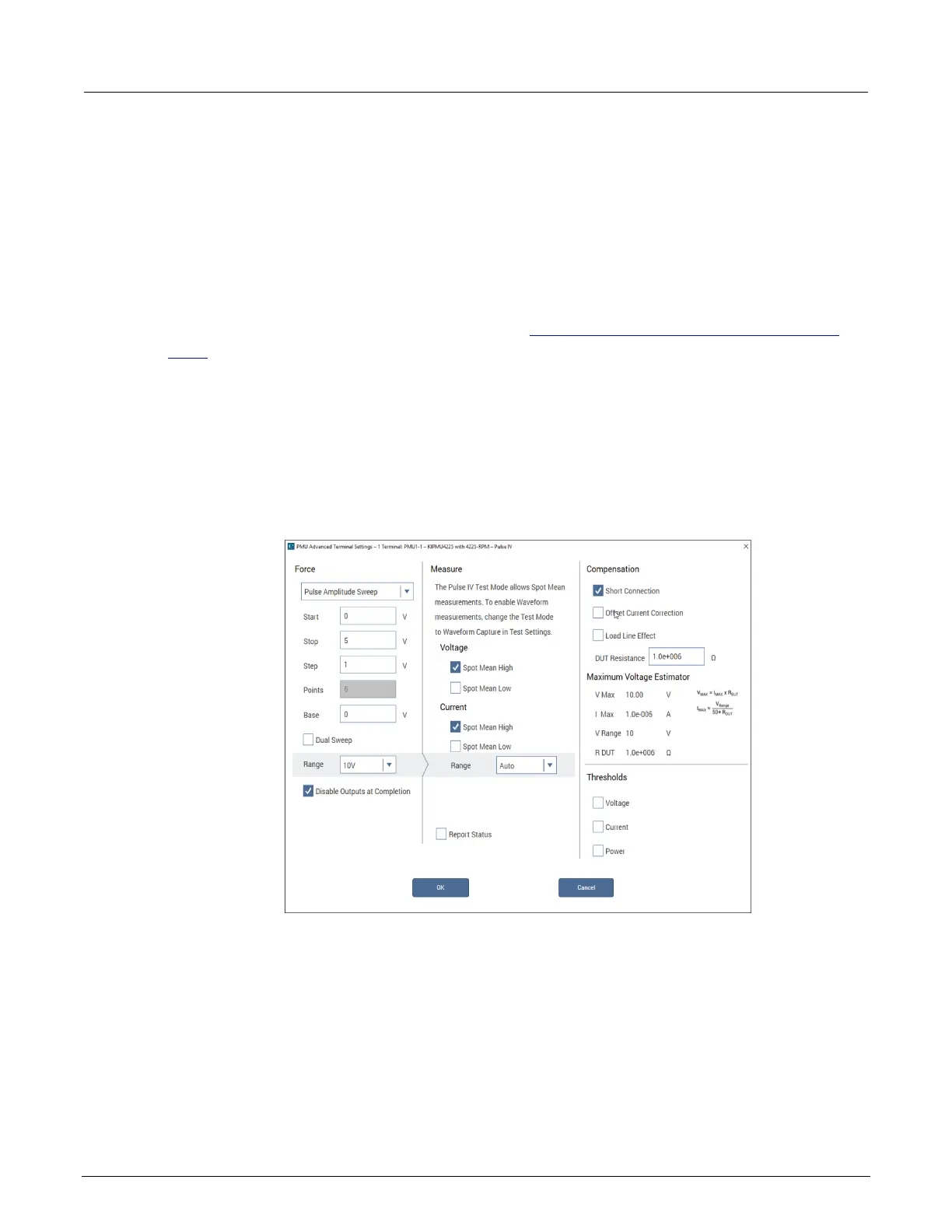
PMU amplitude sweep example (one-channel)
This figure illustrates the advanced terminal settings for a pulse amplitude sweep using a single
PMU channel.
Figure 56: One-channel PMU amplitude sweep
The following figure illustrates the Advanced Test Settings for a six-step pulse amplitude sweep. In
this sweep, the PMU Advanced Terminal Settings dialog (see previous figure) defines the test
parameters.
In the Pulse Timing Preview, there are two graphs. The bottom graph, labeled “Entire Test,” shows
the complete test. This graph shows each sweep and step point for the entire test. The graphed
points reflect the PMU Advanced Settings for the PMU channel in the test. The cursor (the pair of
vertical black lines on the Entire Test graph) defines the content of the upper graph labeled
“Expanded View”). The test settings shown in the previous figure define the six sweep points that are
 Loading...