Removal and Inst a l l a t i on Procedures
6-- 8
TDS5000B Series Se r vi c e Manual
Equipment Required. Most modules in the TDS5000B Digital Oscilloscope can be
removed with a screwdriver handle mounted with a size T-15, TORX screwdriver
tip. Use this tool whenever a procedure step i nst ruc t s you to remove or install a
screw unless a different size screwdriver is specified in that st e p. All equipment
required to r e m ove and reinstal l each module is listed in the first step of the
procedure.
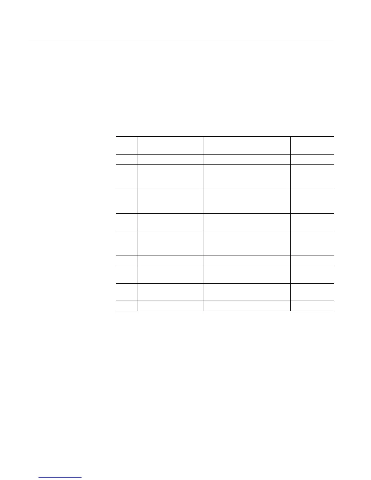
Table 6 -- 3: Tools required for module removal
Item
no.
Name Description
General tool
number
1 Screwdriver handle Accepts TORX-driver bits 620-440
2 T-10 TORX tip Used for removing the electrical or
optical module chassis. TORX-driver
bit for T-10 size screw heads
640-235
3 T-15 TORX tip Used for removing most oscillosc ope
screws. TORX-driver bit for T-15 size
screw heads
640-247
4
1
/
8
inch flat-bladed screw-
driver
Screwdriver for unlocking cable
connectors
Standard tool
5 #0 Phillips screwdriver Screwdriver for removing small
Phillips screws, CD, floppy & hard
drive
Standard tool
6 Angle-Tip Tweezers Used to remove front panel knobs Standard tool
7
3
/
16
inch open-end wrench
Used to remove the rear panel nut
posts
Standard tool
8
5
/
16
inch open-end wrench
Used to remove the rear panel nut
posts
Standard tool
9 MA-800G Soldering Aid Used to remove the front panel trim Standard tool

 Loading...


