Removal and Inst a l l a t i on Procedures
6-- 28
TDS5000B Series Se r vi c e Manual
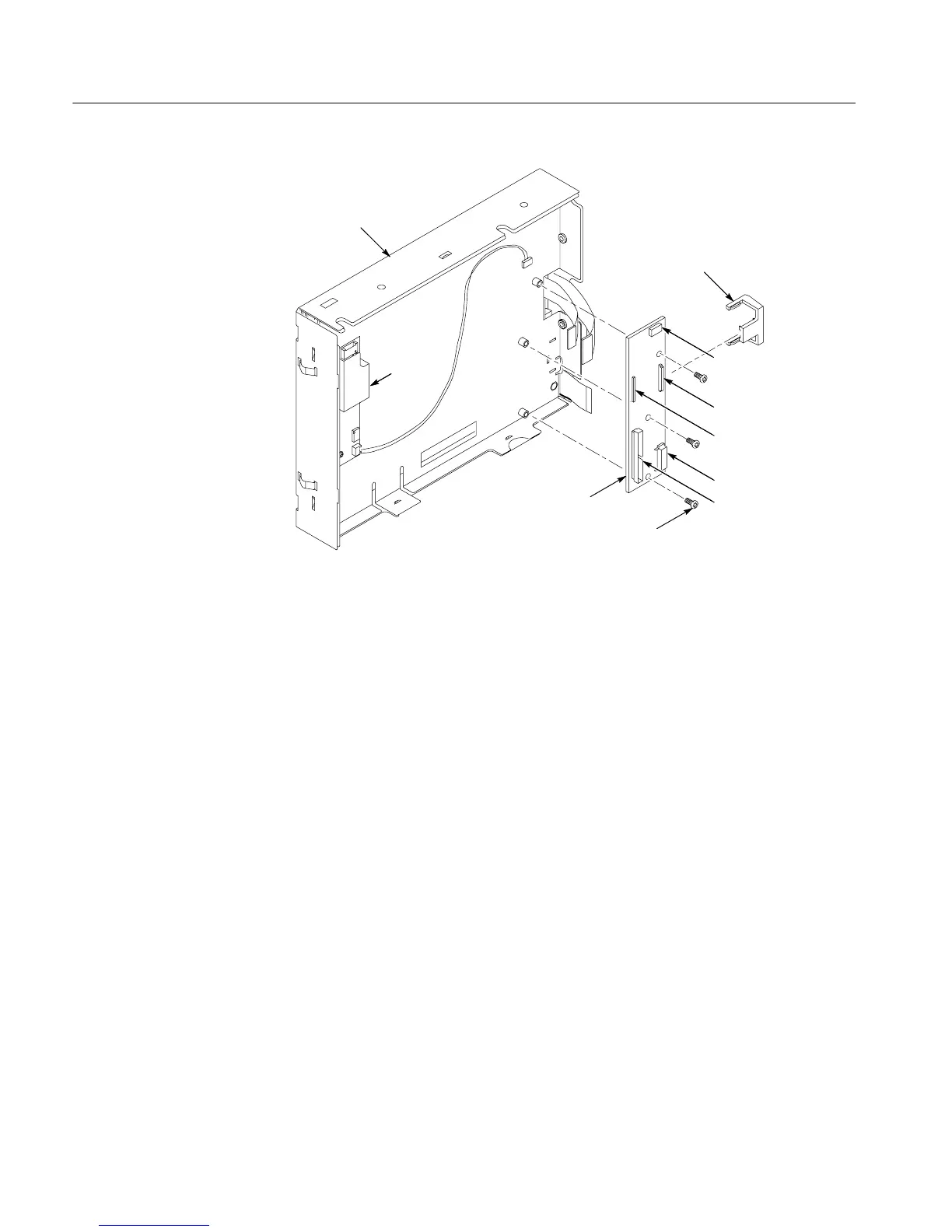
Back view
J7
J4
J6
J1
Display module
Display
adapter board
T--15 TORX
drive screw (3)
J5
Inverter
board
Connector clip
Figure 6--13: Displa y adapter board removal
1. Locate module to be removed: Loca t e the On/Standby Switch power flex
circuit in the locator dia gr a m Internal Modules, Figure 6--7, page 6--19.
Additional modules to be remove d:
! Trim (front panel )
! Display assembly
2. Orient the assembl y : Set the display adapter so the ba c k is down on the work
surface and t he front is facing you.
3. Remove the On/Standby Switch power flex circuit: Se e Figure 6--14, on
page 6--29.
a. Peel the On/St a ndby switch power flex circuit away from the front of the
display assembly.
b. Di sc onne c t the flex circuit from J7 on the Display Adapt e r circuit boar d.
c. Grasp the flex circuit and pull it out of the Display assembly.
4. Reinstallation: Do the followi ng procedure to reinstall the On/Standby
Switch.
a. Remove the prote c t i ve backing on the power f l e x circuit.
On/Standby Switch Power
Flex Circuit Removal

 Loading...


